Recommended way is to use labeled value display. As formatted strings like “10 %” not stored to history graph.
Hi @Jamin…thanks for detailed explanation I am new to blynk and trying to implement this project on my home network. I uploaded code onto esp8266 and app says that device is offline.
I am using this code for wifi_credentials.h library
#ifndef CREDENTIALS_H
#define CREDENTIALS_H
char WIFI_SSID = “my_wifi”; // SSID
char WIFI_PASS = “xxxxxxxxxx”; //Password
#endif
and in settings.h, i just placed my AUTH code.
Please Let me know if i need more changes in code. Thanks
Use
#define WIFI_PASS "xxxx"
Instead and you’re sweet!
Just make sure you put it in your library folder. I also exclude the #ifndef directives etc too. I just have the two lines of credentials.
I’ll update the readme with proper instructions.
1 Like
thank u so much for prompt reply. Really appreciate that
1 Like
Updated docs and used your addition for safety  Cheers
1 Like
Hi @Jamin,
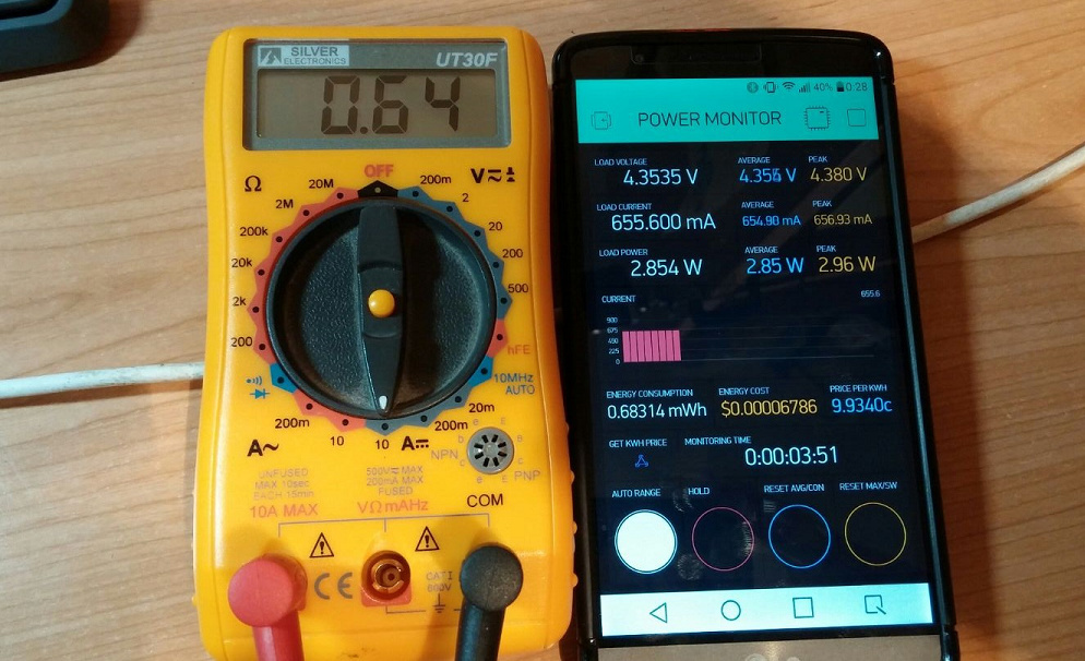
I have been playing with your project and the INA219 sensor, thanks for sharing this amazing project!
The results using my tester and the INA219 are pretty similar, see below:
Voltage: 4.34 V vs 4.3590 V
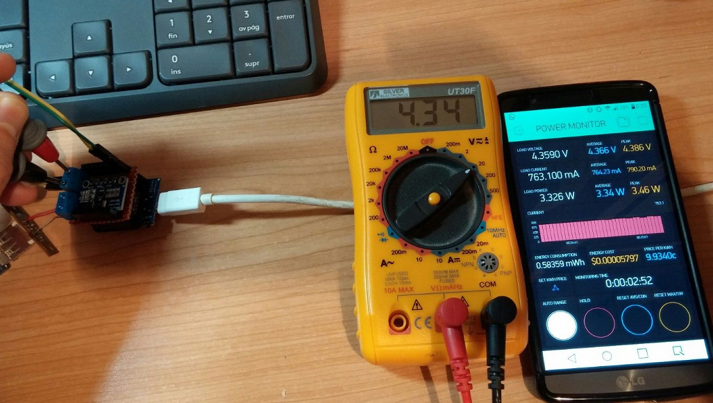
Current: 640 mA vs 655 mA (feeding a thirsty power-bank)
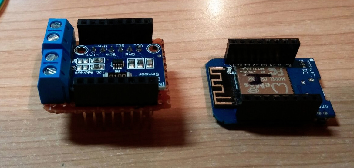
My set up:
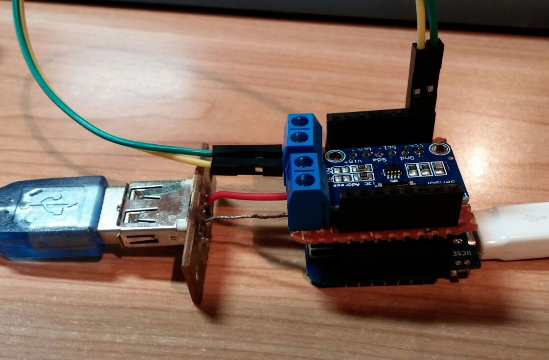
“Plug-and-play” shield (I have cut the board a little bit to be able to do this shield)
Kind regards
1 Like
That’s great to hear you’re enjoying the project! It’s by far one of my favourite. 
Are you running the latest GitHub code? It looks like you have lower resolution Power values.
I could also look at adding a calibration setting for voltage and current? Then calibrate it to a high accuracy meter
1 Like
Hi mate,
Yes, I’m running latest code (I guess… Lol)
At the moment, there’s no need to add a calibration setting, I’m just playing around with the sensor, nothing interesting (at the moment… )
)
BR!
1 Like
Thanks… Beautiful project!
Is it possible monitoring power for 220 V ?
What must i change?
Thank you so much!
The INA219 is a DC-DC sensor with 26V max input…
I can’t (and wont) advise on how to work with mains as it too dangerous to be giving out information.
However, if you can find a sensor which works with AC mains, then give it a shot at your own risk.
Thanks for the answer!
But finding the sensor for AC (I’m an electrician), can I use the same Sketch?
You won’t be able to just use it as it is because it is designed for the INA219 I2C sensor.
You will need to strip out all the INA219 code and replace it with the code for hte sesnor you settle on. You may need to look at a non-invasive current sensor. The clamp/ring type and look up the code needed to run it, then you can insert that code in place of the INA219 code.
Updates:
v1.3 - https://github.com/jaminNZx/ESP8266-Power-Monitor/releases/latest
- Updated all simpleTimer functions to use newly discovered short hand syntax (thanks @Gunner)
- Lowered lines of code by 75 so faster compiling.
- No other functionality changes.
2 Likes
Thak you so much !!
Dear @Jamin,
first of all I would like to send you a BIG thanks for your fine project that you shared with us.
I have a question, something that I can not understand in your code / sketch. The following is a copy - paste from your code and I can not understand it. What are you doing with these? As far as I understood, these are running only once, Am I right? Please at your convenience, explain it to me,
Thanks and Best Regards,
Mike Kranidis
  // gather voltage averages
  loadvoltage_AVG[loadvoltage_AVG_cycle] = loadvoltage;
  loadvoltage_AVG_cycle++;
  if (loadvoltage_AVG_cycle == AVG_DEPTH_VOLTAGE) loadvoltage_AVG_cycle = 0;

  // gather current averages
  current_AVG[current_AVG_cycle] = current_mA;
  current_AVG_cycle++;
  if (current_AVG_cycle == AVG_DEPTH_CURRENT) current_AVG_cycle = 0;

  // gather power averages
  power_AVG[power_AVG_cycle] = power;
  power_AVG_cycle++;
  if (power_AVG_cycle == AVG_DEPTH_POWER) power_AVG_cycle = 0;
}
1 Like
Hey that function runs every second. So it’s taking the current value (for each loadvoltage, current and power) and adds it to an array. Then each new second when it runs, it cycles through the array slots until its full then goes back to the start.
Then you can take the total of the array value, add it up and divide it by the number of values in the array to get the average value.
Dear @Jamin
what comprise the function? Sorry to bother you further but is the bellow function? And how do you call it each seconds ? I can not understand …
 // gather voltage averages
  loadvoltage_AVG[loadvoltage_AVG_cycle] = loadvoltage;
  loadvoltage_AVG_cycle++;
  if (loadvoltage_AVG_cycle == AVG_DEPTH_VOLTAGE) loadvoltage_AVG_cycle = 0;
P.S. I am not programmer… If it is hardware then no problem!
Everything in lines 30 to 62 are called at 1s intervals from the timer call in setup at line 279.
2 Likes
Ahhhhh OK Costas. I missed the point and the brackets … I am a poor man…
do you have the photo now sir?