I’ve deployed a garage door controller (two doors). It uses a Photon and the Photon relay shield, magnetic switches for door sensors, and a Blynk app. The app has a button and led status for each door. Fun project. Works great!

4 Likes
Nice. Thanks for sharing. By the way do you use local server or cloud?
1 Like
Very cool technology! I’m using the cloud for now.
A W E S O M E 
Have you shared your app with relatives, so that you are not the only Master of the Door ? 
1 Like
I’m guessing that depends on what car is in there, if it’s a classic I’d be the only master haha.
Can you share maybe some code and schematics? I’d like to adopt this to open our garden door via our cell phones.
Here’s the current GARAGE app code. The project needs to include the BLYNK and SPARKCOREPOLLEDTIMER libraries. You should be able to get an idea from the pins how things are connected/wired, but let me know if you still need a schematic and I’ll post it shortly, I’d need to draw it on a napkin first! You may also need to refer to the relay shield data sheet https://docs.particle.io/datasheets/photon-shields/#relay-shield. Make sure you fill in your auth key too.
indent preformatted text by 4 spaces
// This #include statement was automatically added by the Particle IDE.
#include "blynk/blynk.h"
#include "SparkCorePolledTimer/SparkCorePolledTimer.h"

char auth[] = "";

// door 1 sensor and control
const int magSwitch1 = D0;
const int relaySwitch1 = D3;
// door 2 sensor and control
const int magSwitch2 = D1;
const int relaySwitch2 = D4;

// door 1 status
int magStatus1 = 0;
int ledStatus1 = 0;
// door 2 status
int magStatus2 = 0;
int ledStatus2 = 0;

// timeout in milliseconds
SparkCorePolledTimer updateTimer(1000);

void OnTimer(void) {
    sendDoorStatus();
}

void setup() {
    Serial.begin(9600);
    Blynk.begin(auth);
    while (Blynk.connect() == false) {
        // Wait until connected
    }

    pinMode(relaySwitch1, OUTPUT);
    pinMode(relaySwitch2, OUTPUT);
    pinMode(magSwitch1, INPUT_PULLDOWN);
    pinMode(magSwitch2, INPUT_PULLDOWN);

    updateTimer.SetCallback(OnTimer);
}

void sendDoorStatus() {
    Blynk.virtualWrite(V5, ledStatus1);
    Blynk.virtualWrite(V6, ledStatus2);
}

void loop() {
    Blynk.run();

    //constantly monitor the door magnetic switch status (garage door open or closed)
    magStatus1 = digitalRead(magSwitch1);
    magStatus2 = digitalRead(magSwitch2);

    if (magStatus1 == HIGH) {
        ledStatus1 = 1023; // 100% brightness
        //Serial.println("LED1: high");
    } else {
        ledStatus1 = 0;
        //Serial.println("LED1: low");
    }
    if (magStatus2 == HIGH) {
        ledStatus2 = 1023;
    } else {
        ledStatus2 = 0;
    }

    updateTimer.Update();
}So here’s a “back of napkin” wiring diagram.

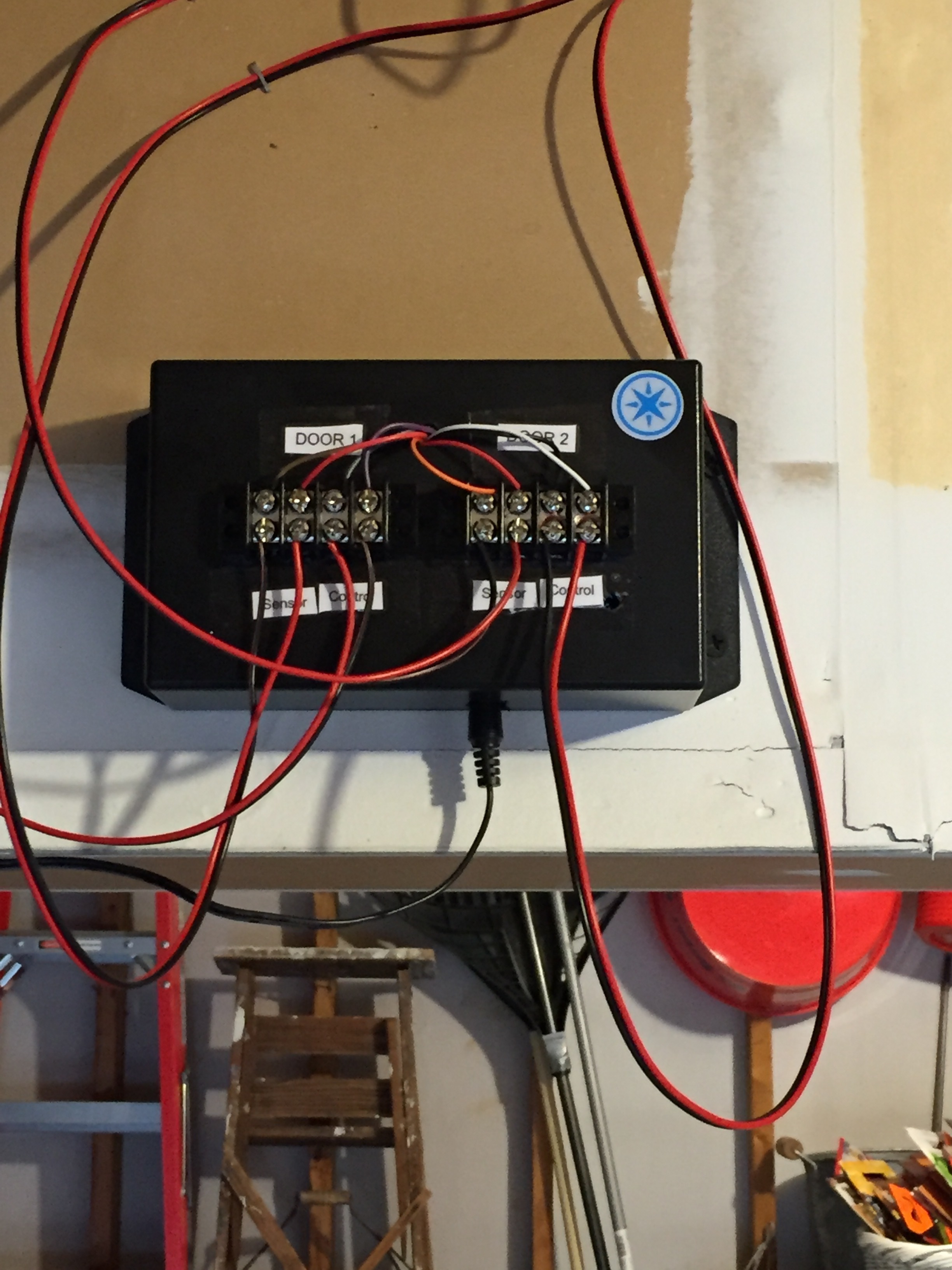
Please keep in mind that this diagram is in the context of using the Relay Shield. The relay connections are to the Normally Open (NO) and Common terminals.
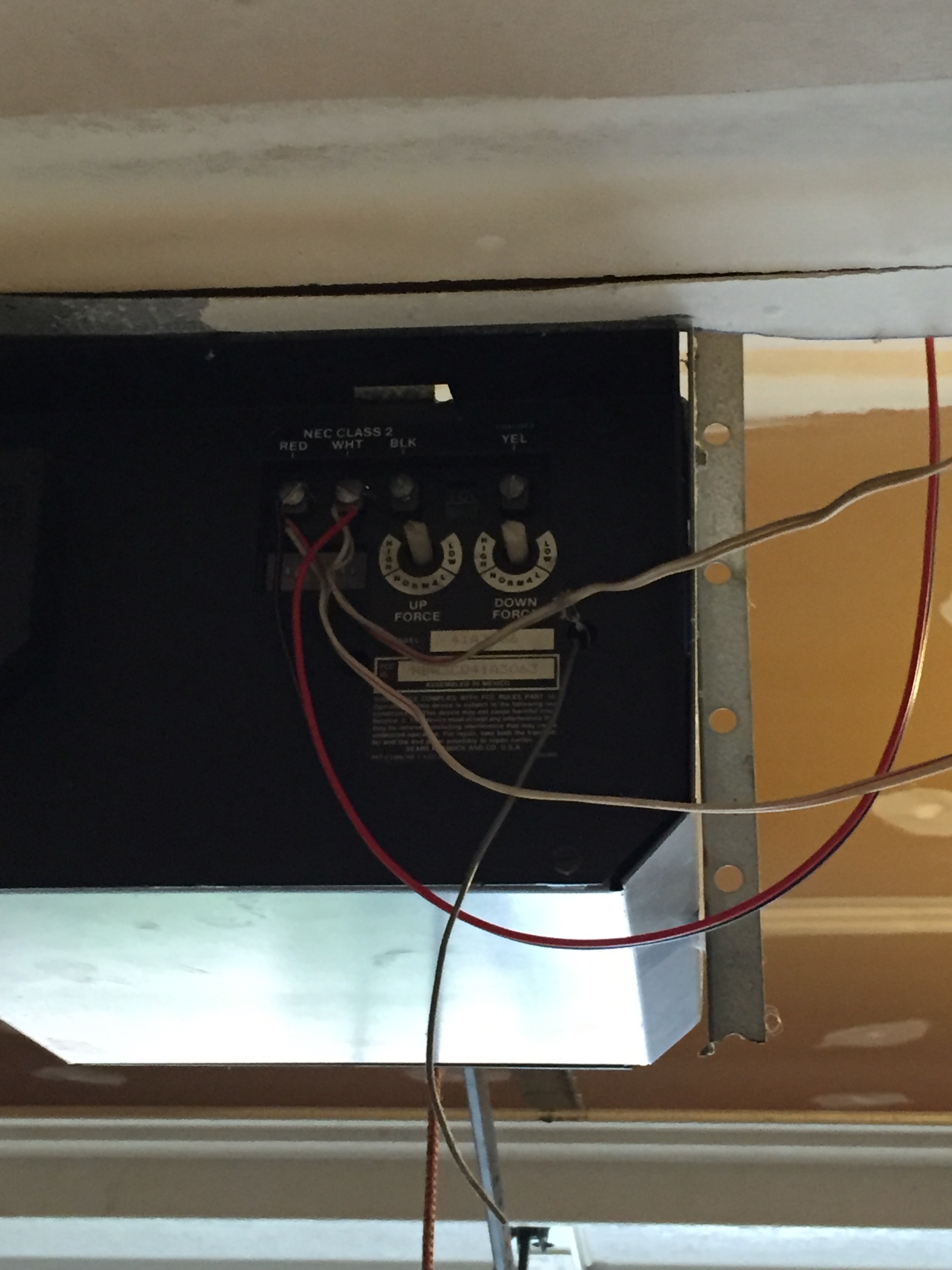
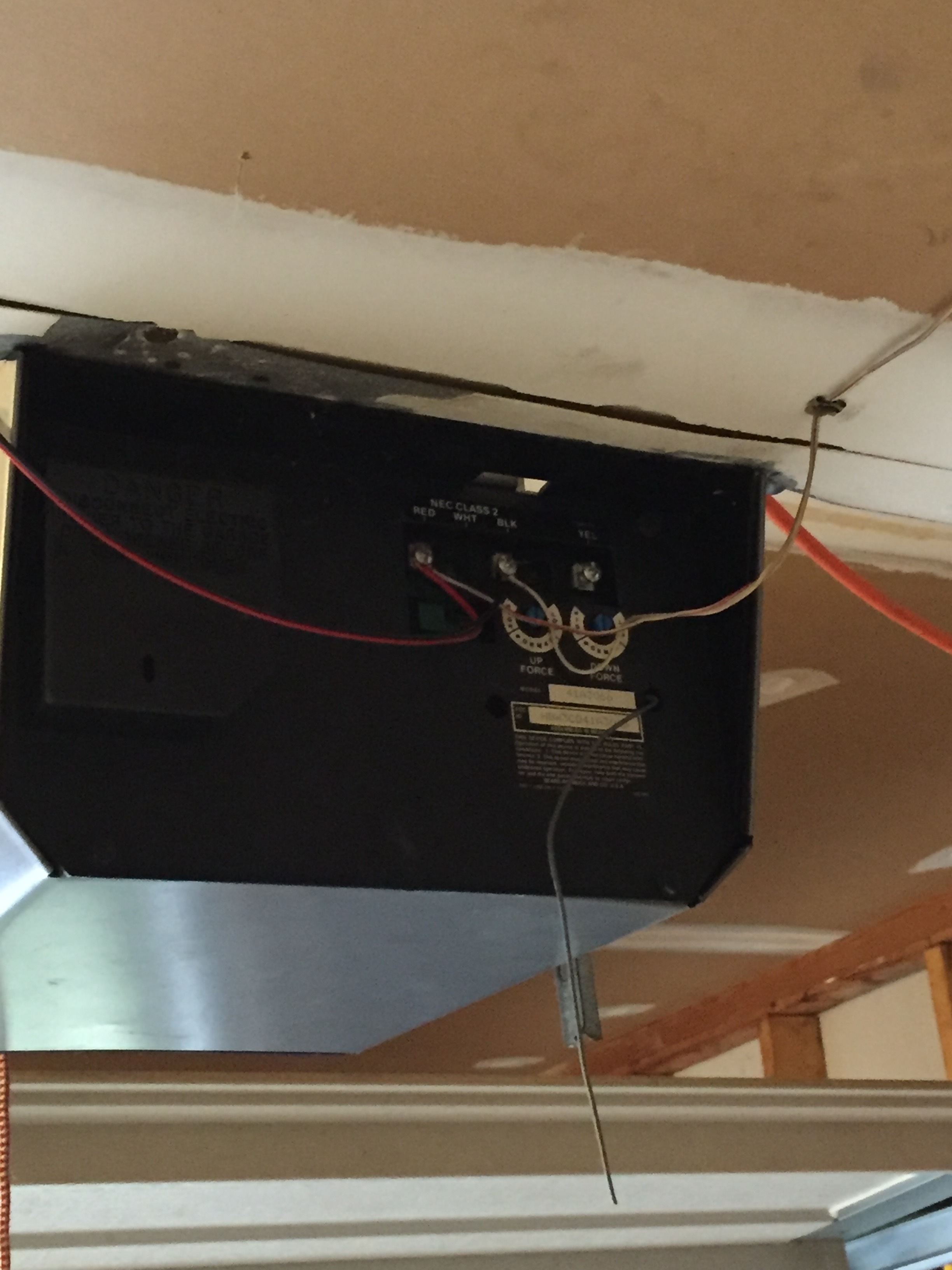
The door control connections go to the garage door motor switch connectors. The sensor connection digital inputs go to the magnetic switch Normally Open (NO) terminals. The magnetic switch common terminals go to the ground pin connections. There is no polarity to any of these connections though.
Is it possible to use the same project with ESP8266? If yes what are the library to use. Please advice.
Thanks
I think you could do it, but you want to choose a ESP8266 version which has 4 GPIO pins at least for this project with 2 doors and 2 sensors.
So you could make use of everything but ESP-01, because he has only 2 GPIO pins.
Good luck and write here, if you did it.
I’m currently using an esp-07 for controlling my garage door. I’ll edit this post to add the code when I’m on my laptop. It uses a relay to simulate a press of the switch, and a magnetic reed switch to read the state of the door (up/down). I have a version using WiFiManager to collect the wifi/blynk info, but it is currently untested.
Edit Here is the code
Original Version:
//#define BLYNK_PRINT Serial //comment out after I know this works

#include <SimpleTimer.h>
#include <ESP8266WiFi.h>
#include <BlynkSimpleEsp8266.h>


// Declare the timer object
SimpleTimer timer;

// You should get Auth Token in the Blynk App.
// Go to the Project Settings (nut icon).
char auth[] = "AUTH TOKEN HERE";
int DoorState = 0;  //Initially Set Door To "OPEN"
int LockOut = 0; //set switch lockout to prevent bounce

/*
 *                  PIN ASSIGNMENTS
 *
 * Virtual Pin V1 is the OPEN/CLOSE Button Widget (Momentary)
 * Virtual Pin V5 is the OPEN/CLOSE Status Indicator Widget (Value Display)
 * 8266 GPIO Pin 4 (D2 on nodemcu/05 on breakout board) is the Garage Door Actuator Relay Switch
 * 8266 GPIO Pin 5 (D1 on nodemcu/04 on breakout board)  is the Garage Door Sensor Switch
 * Add Push Notification Widget for Controller Offline notifications
 *
 *                     HARDWARE
 *
 *  -ESP-07 8266 WIFI Chip with necessary power supply
 *
 *  -Magnetic reed Switch wired NORMALLY CLOSED between GPIO5 pin (Pulled high with 1.5k resistor to VCC) and Ground
 *   (Switch is opened when door is closed)
 *
 *  -3v relay controlled by GPIO4 (via resistor to 2N2222 transistor gate) **Don't forget the snubber diode between the +/- leads on the relay
 *
 *  -Wires spliced into Garage door actuator switch from 3v relay (wired NORMALLY OPEN) for simulating switch press
 */

void setup()
{

 pinMode(5,INPUT);         // Garage Door Sensor Switch (GPIO5)**Add External Pullup 1.5k OHM
 digitalWrite(5,HIGH);     // Set Initial Switch State (HIGH)
 pinMode(4,OUTPUT);        // Garage Door Actuator Relay Switch (GPIO4)
 digitalWrite(4,LOW);      // Set Relay Switch Low (GPIO4)
 //Serial.begin(9600); // See the connection status in Serial Monitor for debugging

	Blynk.begin(auth, "SSID", "PASS", "SERVER");

	while (Blynk.connect() == false) {
		// Wait until connected
	}

timer.setInterval(1500, WriteDoorState);  //Create recurring timer to send the Door Status (OPEN/CLOSED) to the Blynk App

}

 BLYNK_WRITE(V1) // Button Widget WRITING to V1 (OPEN/CLOSE Button Widget)
    {
          int virtualPinValue =  param.asInt(); // here you assign Virtual Pin 1 value to a variable
          if ( virtualPinValue == 1 ){  //here you check if the V1 value is 1 (HIGH)
            ActuateDoorSwitch ();       //Call Door Actuator routine if button is pressed
          }
    }

void loop()
{
  Blynk.run();                    //Init Blynk
  timer.run();                    //Init Timer
  DoorState = digitalRead(5);     //Read the state of the Door switch (is open or closed?)

  if (WiFi.status() == 6)		  //Check Connection Status, reset 8266 if WiFi has disconnected
  {
	  ESP.reset();
  }
}

void WriteDoorState ()            //sends door state status to Blynk App (Value Display?)
{
  if(DoorState){                  //if input is high (1), then door is closed
    Blynk.virtualWrite(V5,"DOWN");
  }
  else {                          //if input is low (0), then door is open
    Blynk.virtualWrite(V5,"UP");
  }
}

void ActuateDoorSwitch ()
{
  if (LockOut == 0){
    digitalWrite(4,HIGH);              //closes door actuator switch via relay
    timer.setTimeout(1000,SwitchOff);   //sets 1 second timer to re-open switch
    LockOut = 1;						//set switch lockout bit
    timer.setTimeout(10000,SwitchUnLock); //10 second switch debounce timer
  }


}

void SwitchOff ()
{
  digitalWrite(4,LOW);               //turn off relay to open door actuator switch
}

void SwitchUnLock()
{
  LockOut = 0;						//reset lockout bit
}
WiFi Manager Version:
 /*
 *    GARAGE DOOR OPENER WITH BLYNK AND WIFI MANAGER
 *
 *                  PIN ASSIGNMENTS
 *
 * Virtual Pin V1 is the OPEN/CLOSE Button Widget (Momentary)
 * Virtual Pin V5 is the OPEN/CLOSE Status Indicator Widget (Value Display)
 * 8266 GPIO Pin 4 (D2 on nodemcu/05 on breakout board) is the Garage Door Actuator Relay Switch
 * 8266 GPIO Pin 5 (D1 on nodemcu/04 on breakout board)  is the Garage Door Sensor Switch
 * Add Push Notification Widget for Controller Offline notifications
 *
 *                     HARDWARE
 *
 *  -ESP-07 8266 WIFI Chip with necessary power supply
 *
 *  -Magnetic reed Switch wired NORMALLY CLOSED between GPIO5 pin (Pulled high with 1.5k resistor to VCC) and Ground
 *   (Switch is opened when door is closed)
 *
 *  -3v relay controlled by GPIO4 (via resistor to 2N2222 transistor gate) **Don't forget the snubber diode between the +/- leads on the relay
 *
 *  -Wires spliced into Garage door actuator switch (at back of motor) from 3v relay (wired NORMALLY OPEN) for simulating switch press
 */


#include <ESP8266WiFi.h>          //https://github.com/esp8266/Arduino
#include <DNSServer.h>            //needed for library
#include <ESP8266WebServer.h>
#include <WiFiManager.h>          //https://github.com/tzapu/WiFiManager
#include <BlynkSimpleEsp8266.h>
#include <FS.h>                   //this needs to be first, or it all crashes and burns...
#include <ArduinoJson.h>          //https://github.com/bblanchon/ArduinoJson
#include <SimpleTimer.h>


//define your default values here, if there are different values in config.json, they are overwritten.
char blynk_server[40]= "cloud.blynk.cc" ;
char blynk_port[6] = "8442";
char blynk_token[40] = "YOUR_BLYNK_TOKEN";

int DoorState = 0;  //Initially Set Door To "OPEN"
int LockOut = 0; //set switch lockout to prevent bounce
bool shouldSaveConfig = false;  //flag for saving data
SimpleTimer timer;  // Declare the timer object

//callback notifying us of the need to save config
void saveConfigCallback () {
  shouldSaveConfig = true;
}


void setup() {
  // put your setup code here, to run once:

  pinMode(5, INPUT);         // Garage Door Sensor Switch (GPIO5)**Add External Pullup 1.5k OHM
  digitalWrite(5, HIGH);     // Set Initial Switch State (HIGH)
  pinMode(4, OUTPUT);        // Garage Door Actuator Relay Switch (GPIO4)
  digitalWrite(4, LOW);      // Set Relay Switch Low (GPIO4)


  //read configuration from FS json

  //clean FS, for testing
 //SPIFFS.format();

if (SPIFFS.begin()) {
if (SPIFFS.exists("/config.json")) {
  //file exists, reading and loading
  File configFile = SPIFFS.open("/config.json", "r");
  if (configFile) {
size_t size = configFile.size();
// Allocate a buffer to store contents of the file.
std::unique_ptr<char[]> buf(new char[size]);

configFile.readBytes(buf.get(), size);
DynamicJsonBuffer jsonBuffer;
JsonObject& json = jsonBuffer.parseObject(buf.get());
if (json.success()) {

  strcpy(blynk_server, json["blynk_server"]);
  strcpy(blynk_port, json["blynk_port"]);
  strcpy(blynk_token, json["blynk_token"]);

} else {
 //failed to load json config
}
  }
}
  } else {
//failed to mount FS
  }
  //end read


  // The extra parameters to be configured (can be either global or just in the setup)
  // After connecting, parameter.getValue() will get you the configured value
  // id/name placeholder/prompt default length
  WiFiManagerParameter custom_blynk_server("server", "blynk server", blynk_server, 40);
  WiFiManagerParameter custom_blynk_port("port", "blynk port", blynk_port, 5);
  WiFiManagerParameter custom_blynk_token("blynk", "blynk token", blynk_token, 33);

  //WiFiManager
  //Local intialization. Once its business is done, there is no need to keep it around
  WiFiManager wifiManager;

  //set config save notify callback
  wifiManager.setSaveConfigCallback(saveConfigCallback);

  //add all your parameters here
  wifiManager.addParameter(&custom_blynk_server);
  wifiManager.addParameter(&custom_blynk_port);
  wifiManager.addParameter(&custom_blynk_token);

  //reset settings - for testing
  //wifiManager.resetSettings();

  //set minimum quality of signal so it ignores AP's under that quality
  //defaults to 8%
  //wifiManager.setMinimumSignalQuality();

  //sets timeout until configuration portal gets turned off
  //useful to make it all retry or go to sleep
  //in seconds
  wifiManager.setTimeout(300);

  //fetches ssid and pass and tries to connect
  //if it does not connect it starts an access point with the specified name
  //and goes into a blocking loop awaiting configuration
  if (!wifiManager.autoConnect("wellbuilt", "project")) {
delay(3000);
//reset and try again, or maybe put it to deep sleep
ESP.reset();
delay(5000);
  }

  //if you get here you have connected to the WiFi

  //read updated parameters
  strcpy(blynk_server, custom_blynk_server.getValue());
  strcpy(blynk_port, custom_blynk_port.getValue());
  strcpy(blynk_token, custom_blynk_token.getValue());

  //save the custom parameters to FS
  if (shouldSaveConfig) {
DynamicJsonBuffer jsonBuffer;
JsonObject& json = jsonBuffer.createObject();
json["blynk_server"] = blynk_server;
json["blynk_port"] = blynk_port;
json["blynk_token"] = blynk_token;

File configFile = SPIFFS.open("/config.json", "w");
if (!configFile) {
}

json.printTo(configFile);
configFile.close();
//end save
  }


  Blynk.config(blynk_token, blynk_server, atoi(blynk_port));
  Blynk.connect();
  timer.setInterval(1500, WriteDoorState);  //Create recurring timer to send the Door Status (OPEN/CLOSED) to the Blynk App
}


BLYNK_WRITE(V1) // Button Widget WRITING to V1 (OPEN/CLOSE Button Widget)
{
	int virtualPinValue = param.asInt(); // here you assign Virtual Pin 1 value to a variable
	if (virtualPinValue == 1) {  //here you check if the V1 value is 1 (HIGH)
		ActuateDoorSwitch();       //Call Door Actuator routine if button is pressed
	}
}

void loop() {
  // put your main code here, to run repeatedly:
Blynk.run();                    //Init Blynk
timer.run();                    //Init Timer
DoorState = digitalRead(5);     //Read the state of the Door switch (is open or closed?)

  if (WiFi.status() == 6)      //Check Connection Status, reset 8266 if WiFi has disconnected
  {
ESP.reset();
  }
}

void WriteDoorState()            //sends door state status to Blynk App (Value Display?)
{
	if (DoorState) {                  //if input is high (1), then door is closed
		Blynk.virtualWrite(V5, "DOWN");
	}
	else {                          //if input is low (0), then door is open
		Blynk.virtualWrite(V5, "UP");
	}
}

void ActuateDoorSwitch()
{
	if (LockOut == 0) {
		digitalWrite(4, HIGH);              //closes door actuator switch via relay
		timer.setTimeout(1000, SwitchOff);   //sets 1 second timer to re-open switch
		LockOut = 1;						//set switch lockout bit
		timer.setTimeout(10000, SwitchUnLock); //10 second switch debounce timer
	}
}

void SwitchOff()
{
	digitalWrite(4, LOW);               //turn off relay to open door actuator switch
}

void SwitchUnLock()
{
	LockOut = 0;						//reset lockout bit
}
Hope This Helps. Let me know if you have questions.
@adam3654 I am using WiFiManager with a Wemos D1 Mini and I notice you have changed the string length in WiFiManagerParameter custom_blynk_token(“blynk”, “blynk token”, blynk_token, 33); from 32 to 33. I copied your change and when accessing a new router for the first time via the web portal I can connect to Blynk.
However if I try to reconnect to Blynk it doesn’t have the correct token so I have to flash the sketch again with wifiManager.resetSettings(); enabled. Do you remember making any other changes related to the token and is WiFiManager working ok for your Blynk access?
@Costas The sketch that is shown above (with WifiManager setup) is what I am currently using in my garage, I had it lock up at one point and power cycled the unit, and it re-connected with out issue. One thing that I should edit is
char blynk_token[40] = "YOUR_BLYNK_TOKEN";
should probably be reduced to [33] as well. I was having trouble with the original code which was based on the example. I changed the MQTT stuff over to blynk, and the allocation for the blynk token was 1 character short, and I was changing it in the variable declaration but not the custom parameter declaration. I kept upping it by one and checking the output of a println for debugging.
When the setup runs the first time, blynk is configured directly from the data input from the webpage and stored into the global variables. After reset, they are read from the json file into the global variables and then used for the blink.config. So I’m thinking your problem lies within the “config.json” file and what data is stored to it during the initial setup.
A couple things that may help:
-
If you can replicate the error while plugged in to the computer, can you print the blynk related stuff to the serial monitor to see what has been stored to the “config.json” file after a reset.
-
Double-check the board settings relating to flash and SPIFFS size. When I first tried to use WifiManager, I was compiling my sketches using the “NodeMCU 1.0” board which worked for previous sketches but would fail with the WifiManager examples. I am using ESP-07’s and had to change to the “Generic 8266” board with 1M (512K SPIFFS) flash size. After the change, it worked perfectly.
But other than that, the code I am currently running with is what is shown in my previous post, and it definitely works for me after a reset.
If I can think of anything else, I’ll let you know. Please let me know when you get it running.
Thanks @adam3654 for your detailed reply.
I think you are right about the json file.
@tzapulica has confirmed that the WiFiManagerParameter should have a length of 33 not 32 i.e. to include the terminator.
May I ask about char blynk_token[40] = “YOUR_BLYNK_TOKEN”;
Ignoring the character array size of 40 what does “YOUR_BLYNK_TOKEN” actually mean? At one point I thought the actual text of YOUR_BLYNK_TOKEN was needed as the preloaded text for the field when it brings up the AP as at one point the field was blank and general users wouldn’t know what actually goes in the field.
At one stage I had char blynk_token[34] = " "; and also char blynk_token[34] = “”;
Currently I have it as char blynk_token[34]; The field name does appear in the AP but it must come from somewhere else in the sketch because I think it states “blynk token”.
I’m almost thinking that an actual blynk token goes in here but surely that would defeat the object of what WiFiManager does i.e. allowing users to enter their specific router ssid, pwd and Blynk token.
Meanwhile I will take a look at Generic rather than Wemos and see if that helps. I will also go back to the standalone sketch to be sure it works without Blynk. I think it did and I did go through basic system, then with parameters and then with LED before moving over to my sketch.
I am populating the variable blynk_token with the default value “YOUR_BLYNK_TOKEN” which is only used to set the blynk token textbox on the webpage to the default of “YOUR_BLYNK_TOKEN”. At least that is what I think I’m doing ![]() but it sounds like you are seeing “blynk token”, I don’t have the ability to check what mine does at the moment, and now I’m wondering if “YOUR_BLYNK_TOKEN” is even needed.
but it sounds like you are seeing “blynk token”, I don’t have the ability to check what mine does at the moment, and now I’m wondering if “YOUR_BLYNK_TOKEN” is even needed.
Based on the WeMos website, the 8266 chip is running 4M bytes of flash. So if you try the generic board setting, make sure to set the flash size and SPIFFS allocation correctly. Also, it might be worth trying the other flash setting of the WeMos board “4M (1M SPIFFS)” rather than the 3M SPIFFS option.
I ran the memory checker sketch yesterday and it confirmed 4M flash. I will take a look at generic as I believe others also use generic for Wemos.
I currently have 3M set for SPIFFS in the IDE for Wemos so I will try it with 1M.
The strange thing about YOUR_BLYNK_TOKEN is that in Serial Monitor that is what comes up in debug with Blynk when I fail to connect i.e. after the first successful reset / connection rather than the actual token.
It sounds like the blynk_token variable is not being populated from the config.json file. In my code, there is no debug message if the config file fails to load. Find this spot in the code:
strcpy(blynk_server, json["blynk_server"]);
  strcpy(blynk_port, json["blynk_port"]);
  strcpy(blynk_token, json["blynk_token"]);

} else {
 //failed to load json config
}
and add a Serial.println("Config File Failed to Load"); in the else curlys. Then you can at least see if your config file is loading or not.
@adam3654 fixed now thanks. It was the json, like a numpty I still had the following line in my sketch so it was clearing the SPIFFS every time I reset the wemos:
SPIFFS.format(); //clean FS, for testing
1 Like
Great to hear you have it fixed.
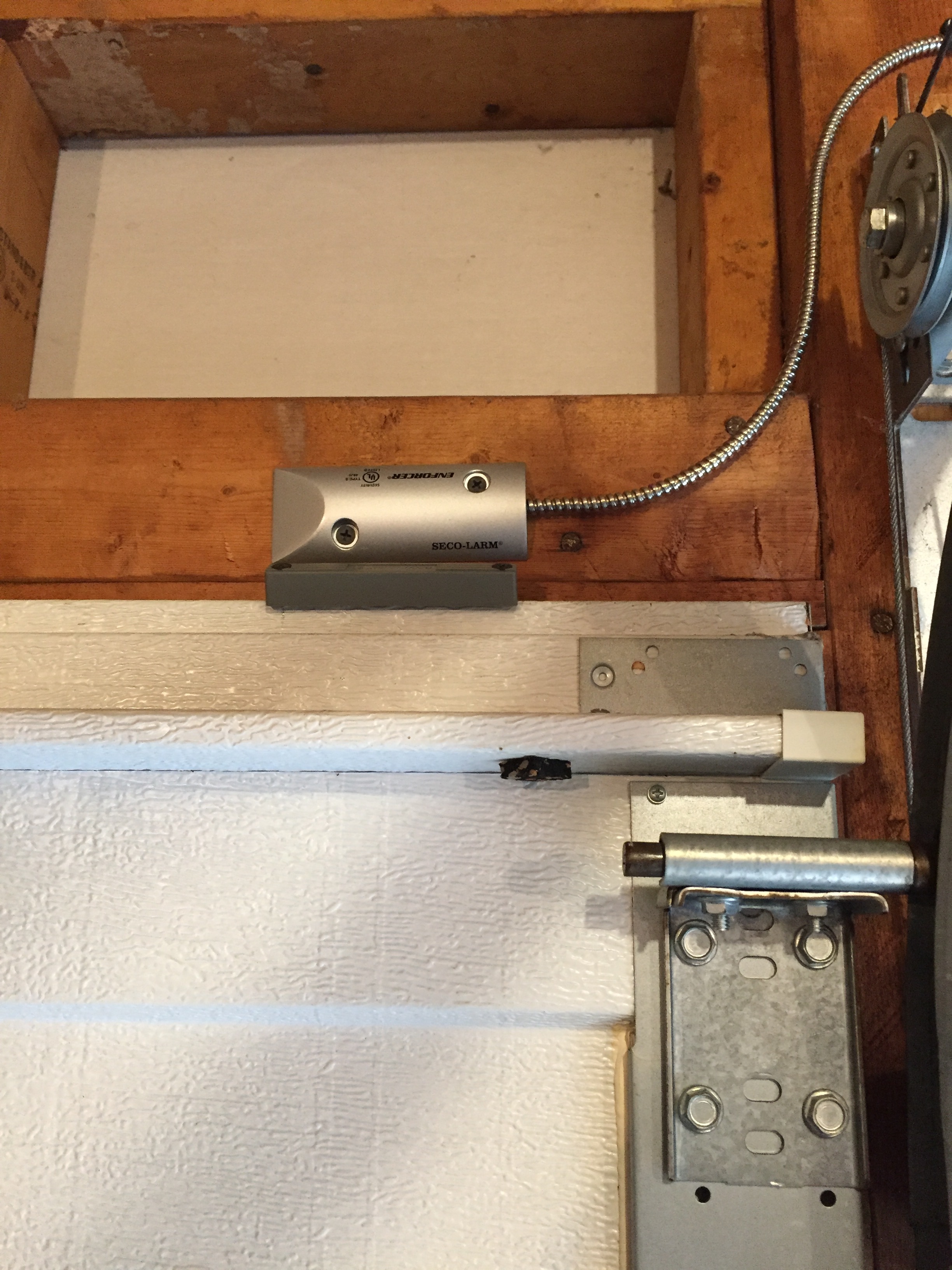
I’ve updated my system with new magnetic door sensors. They are Seco-Larm SM-226L Garage Door Contacts for Closed Circuits ordered from smarthome, http://www.smarthome.com/seco-larm-sm-226l-garage-door-contacts-for-closed-circuits.html. I ended up not using the included ‘L’ shaped aluminum bracket. These are really nice sensors, designed to go on the floor, but I rigged them up for the ‘top’ of each garage door. I’ve included a photo so you can get an idea. The sensor is attached to the wall and the magnet is attached to the top of the door, properly aligned for sensor proximity when closed. There is adequate clearance too when closing. I had a ‘cheesy’ sensor floor setup before, but this is much more professional looking!
1 Like