Not really what we do here But fun looking project. Sorry, I am not experienced with PCB layout.
If you are going to post this as a Project made with Blynk… I recommend you include code and other details… otherwise you are really just asking for help with non-Blynk stuff
Well, at first look, few problems I’ve found on schematic:
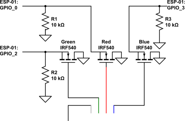
The polarity of output transistors is reversed: The NPN transistor works best while emitter is connected to GND, collector to output. Also MOSFET’s are better for PWM
lack of filtering capacitors on 3.3V regulator. As this (I think) is supposed to work in PWM mode, I would add some 1000uF on voltage input anyway
I was wondering if you could control all three channels with just the ESP-01… and yes, you can, using the RX pin (GPIO3). But still not really Blynk related yet… but add in my zeRGBa code and you are getting closer
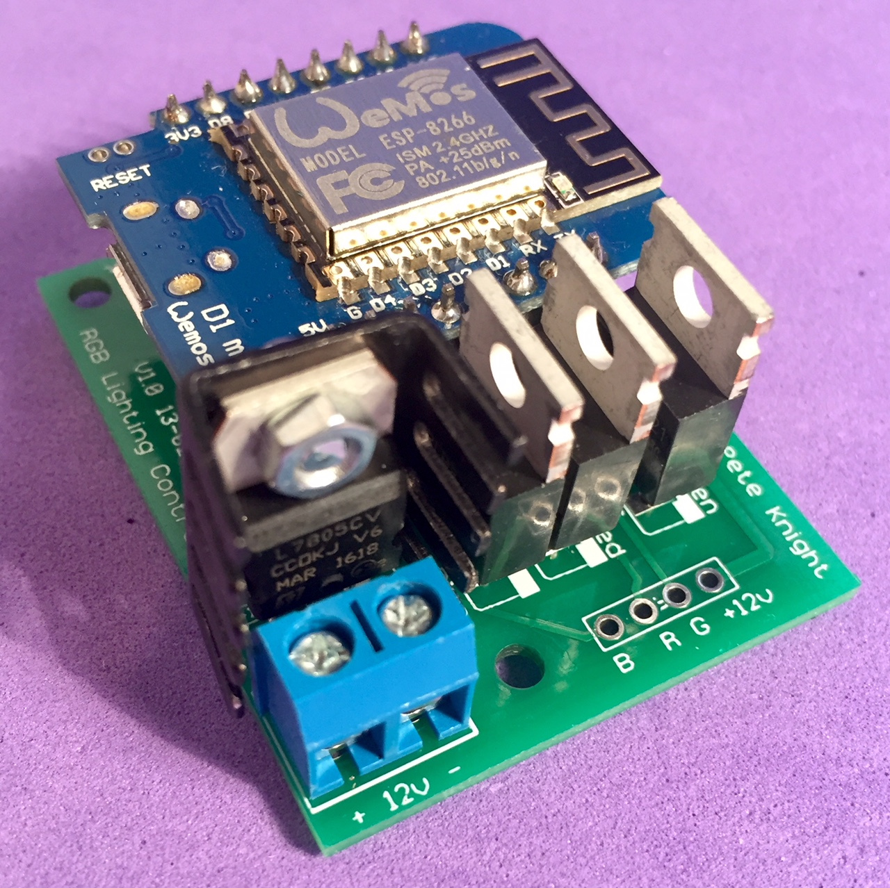
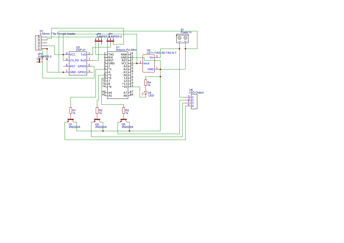
I have to say that you’re making life unnecessarily difficult for yourself by using an Arduino Pro Mini and ESP-01 together. It’s much easier to use a fully-fledged ESP8266 to do everything.
This has a few advantages:
This is basically this circuit from Adafruit but using a Wemos D1 Mini instead of the Arduino Uno and with the addition of an on-board voltage regulator and smoothing capacitor:
Regardless of which circuit you use, I’d recommend the following:
Add some mounting holes to your PCB so that its easier to box-up
Go for wider tracks on the bits of the circuit that will be handling the current of the RGB strip
Allow space for a heatsink on the voltage regulator
Add plenty of screen printed info, you’ll thank yourself for this later
Don’t be tempted to do a ‘copper pour’, the groundplane that it produces could block the Wi-Fi signals to the ESP
I’m using IRLB8721 N-Channel MOSFETs as reccomended in the Adafuit link. They have a Gate threshold voltage of between 1.35 and 2.35v, so work well with either 3.3 or 5v logic levels and can sink much more Drain current than I’ll ever be drawing through them, so they run nice and cool.
Why are you using 90 degree angles ? Not that it makes a difference but 45 degree angles look cooler
And what software is that ? My guess is Eagle ?
And last for cheap pcb orders i recommend JLCPCB.com they charge 2 dollars for 10 pcs when your board is smaller then 10cmx10cm and you can order parts from LCSC at the same time and only pay shipping once for both packages.You also get a coupon on your first order that im sure you will find on the site.
They seem to be a little more expensive, but i just went on their website and they also make custom cases for projects ? Do you have any experience with that ? I have been looking for a service like this.
 But fun looking project. Sorry, I am not experienced with PCB layout.
 while emitter is connected to GND, collector to output. Also MOSFET’s are better for PWM