One of the "LABELED VALUE" display does not work -- HELP -- HELP

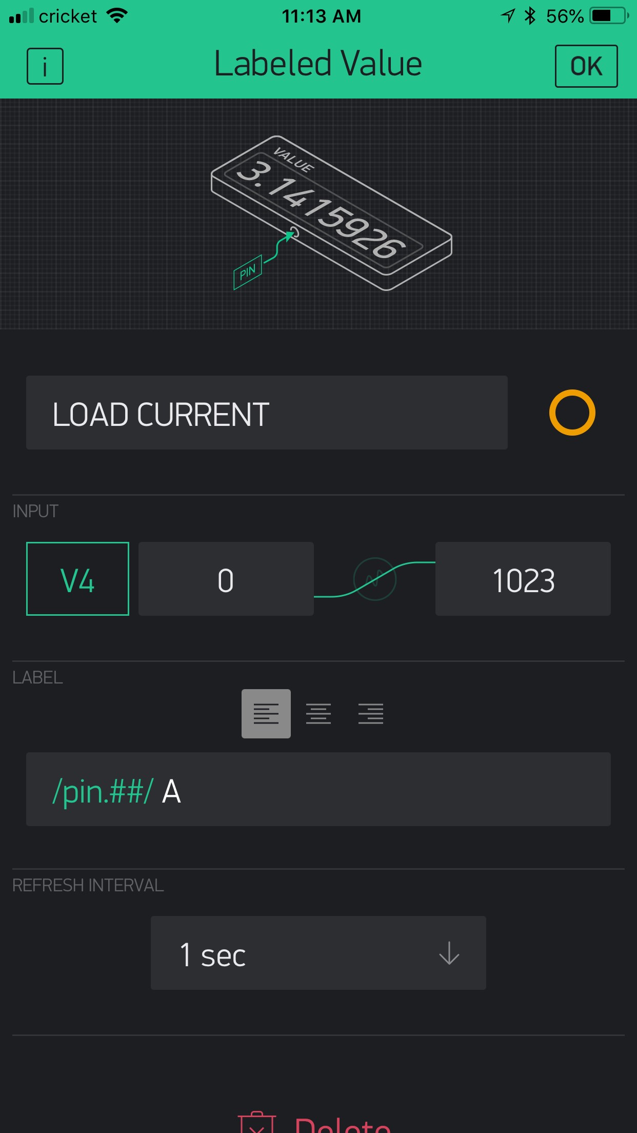
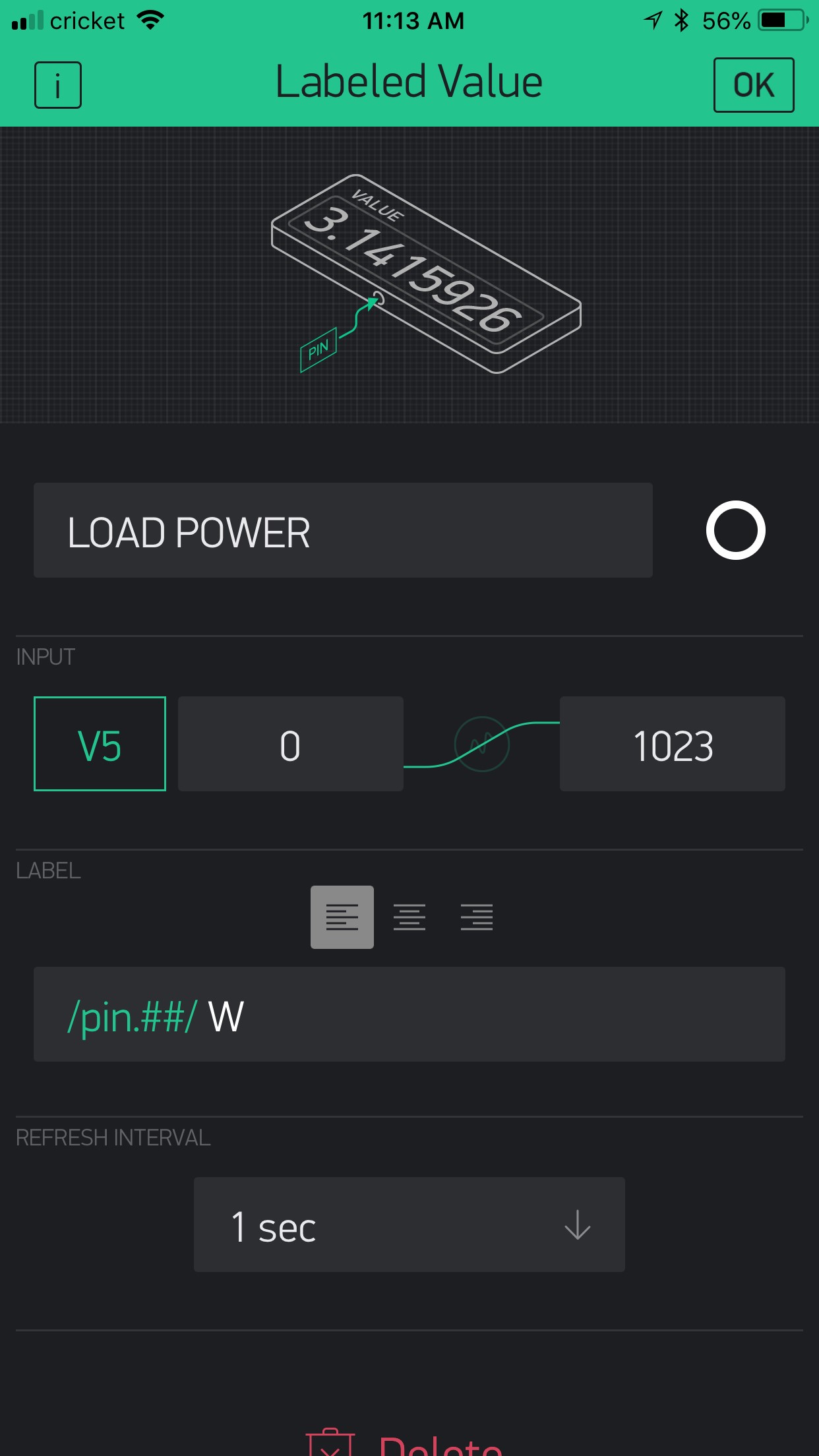
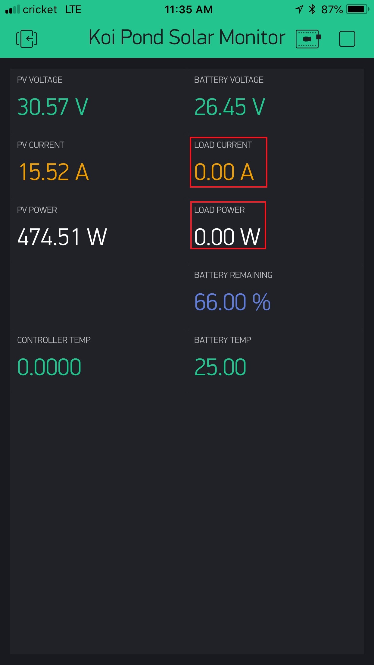
Please help me to identify the cause of why “Load Current” (V4) and “Load Power” (V5) labeled value display are not working? (all other buttons are working fine)

Please treat me as beginner as I’m new to Blynk network.

Here is the code for settings.h file:

/*
   Auth Codes & Wifi info go in the following file.
   Create a new folder in your library dir called 'wifi_credentials'
   and create a new file called 'wifi_credentials.h' and copy the 
   example in the repo. You can use this for all your wifi projects. 
*/
#include <wifi_credentials.h>
/*
     Blynk Auth Codes
*/
#define AUTH                            "put your author code here"
/*
   Local Server Settings
   Comment out to use Cloud Server

/*
  Over The Air Hostname  
*/

/*
   Virtual Pins - Base
*/
#define vPIN_PV_POWER                   V1
#define vPIN_PV_CURRENT                 V2
#define vPIN_PV_VOLTAGE                 V3

#define vPIN_LOAD_CURRENT               V4
#define vPIN_LOAD_POWER                 V5

#define vPIN_BATT_TEMP                  V6
#define vPIN_BATT_VOLTAGE               V7

/*
   Debug. Change to 0 when you are finished debugging.
*/
const int debug             =           1; 
/*
   
*/


And here is the main code.ino file:

// CONNECT THE RS485 MODULE RX->RX, TX->TX.
// Disconnect when uploading code.
#include <ArduinoOTA.h>
#include <BlynkSimpleEsp8266.h>

int timerTask1, timerTask2, timerTask3;
float battBhargeCurrent, bvoltage, ctemp, btemp, bremaining, lpower, lcurrent, pvvoltage, pvcurrent, pvpower;
uint8_t result;

// To add later
//uint8_t result, time1, time2, time3, date1, date2, date3, dateDay, dateMonth, dateYear, timeHour, timeMinute, timeSecond;
//char buf[10];
//String dtString;

// this is to check if we can write since rs485 is half duplex
bool rs485DataReceived = true;

ModbusMaster node;
SimpleTimer timer;

// tracer requires no handshaking
void preTransmission() {}
void postTransmission() {}

// a list of the regisities to query in order
typedef void (*RegistryList[])();
RegistryList Registries = {
  AddressRegistry_3100,
  AddressRegistry_311A,
  AddressRegistry_3300,
};
// keep log of where we are
uint8_t currentRegistryNumber = 0;
// function to switch to next registry
void nextRegistryNumber() {
  currentRegistryNumber = (currentRegistryNumber + 1) % ARRAY_SIZE( Registries);
}

void setup()
{
  Serial.begin(115200);
  // Modbus slave ID 1
  node.begin(1, Serial);
  node.preTransmission(preTransmission);
  node.postTransmission(postTransmission);
  WiFi.mode(WIFI_STA);
#if defined(USE_LOCAL_SERVER)
  Blynk.begin(AUTH, WIFI_SSID, WIFI_PASS, SERVER);
#else
  Blynk.begin(AUTH, WIFI_SSID, WIFI_PASS);
#endif
  while (Blynk.connect() == false) {}
  ArduinoOTA.setHostname(OTA_HOSTNAME);
  ArduinoOTA.begin();

  timerTask1 = timer.setInterval(1000, updateBlynk);
  timerTask2 = timer.setInterval(1000, doRegistryNumber);
  timerTask3 = timer.setInterval(1000, nextRegistryNumber);
}

// --------------------------------------------------------------------------------

void updateBlynk() {
  Blynk.virtualWrite(vPIN_PV_POWER,         pvpower);
  Blynk.virtualWrite(vPIN_PV_CURRENT,       pvcurrent);
  Blynk.virtualWrite(vPIN_PV_VOLTAGE,       pvvoltage);
  Blynk.virtualWrite(vPIN_LOAD_CURRENT,     lcurrent);
  Blynk.virtualWrite(vPIN_LOAD_POWER,       lpower);
  Blynk.virtualWrite(vPIN_BATT_TEMP,        btemp);
  Blynk.virtualWrite(vPIN_BATT_VOLTAGE,     bvoltage);
  
}

void doRegistryNumber() {
  Registries[currentRegistryNumber]();
}

void AddressRegistry_3100() {
  result = node.readInputRegisters(0x3100, 7);
  if (result == node.ku8MBSuccess)
  {
    ctemp = node.getResponseBuffer(0x11) / 100.0f;
    if (debug == 1) {
      Serial.println(ctemp);
      Serial.print("Battery Voltage: ");
    }
    bvoltage = node.getResponseBuffer(0x04) / 100.0f;
    if (debug == 1) {
      Serial.println(bvoltage);

    }
 
      pvvoltage = (long)node.getResponseBuffer(0x00) / 100.0f;
    if (debug == 1) {
      Serial.print("PV Voltage: ");
      Serial.println(pvvoltage);

    }
    pvcurrent = (long)node.getResponseBuffer(0x01) / 100.0f;
    if (debug == 1) {
      Serial.print("PV Current: ");
      Serial.println(pvcurrent);

    }
    pvpower = ((long)node.getResponseBuffer(0x03) << 16 | node.getResponseBuffer(0x02)) / 100.0f;
    if (debug == 1) {
      Serial.print("PV Power: ");
      Serial.println(pvpower);
    }
    battBhargeCurrent = (long)node.getResponseBuffer(0x05) / 100.0f;
    if (debug == 1) {
      Serial.print("Battery Charge Current: ");
      Serial.println(battBhargeCurrent);
      Serial.println();
    }
  } else {
    rs485DataReceived = false;
  }
}

void AddressRegistry_311A() {
  result = node.readInputRegisters(0x311A, 2);
  if (result == node.ku8MBSuccess)
  {
    bremaining = node.getResponseBuffer(0x00) / 1.0f;
    if (debug == 1) {
      Serial.print("Battery Remaining %: ");
      Serial.println(bremaining);

    }
    btemp = node.getResponseBuffer(0x01) / 100.0f;
    if (debug == 1) {
      Serial.print("Battery Temperature: ");
      Serial.println(btemp);
      Serial.println();
    }
  } else {
    rs485DataReceived = false;
  }
}

void AddressRegistry_3300() {
  result = node.readInputRegisters(0x3300, 2);
  if (result == node.ku8MBSuccess)
  {
    stats_today_pv_volt_max = node.getResponseBuffer(0x00) / 100.0f;
    if (debug == 1) {
      Serial.print("Stats Today PV Voltage MAX: ");
      Serial.println(stats_today_pv_volt_max);
    }
    stats_today_pv_volt_min = node.getResponseBuffer(0x01) / 100.0f;
    if (debug == 1) {
      Serial.print("Stats Today PV Voltage MIN: ");
      Serial.println(stats_today_pv_volt_min);
    }
  } else {
    rs485DataReceived = false;
  }
}

void loop()
{
  Blynk.run();
  ArduinoOTA.handle();
  timer.run();
}

please format your code , it’s unreadable

Correct format has been updated, sorry for the cause.

Please help me on how to fix the button V4 and V5 as it does not display anything.

Regards,
key

I’m struggling to understand what you’re doing here. I would have expected these widgets to be Value or Labeled Value Display widgets, not Buttons.

I’d also prefer to see all the code, in one piece, rather than selected segments.

Pete.

Sorry to make you confused as I’m new to the community therefore the term I used was wrong, it should be LABELED VALUE display

I’m trying to read the data from my Solar Charge Controller via RS485.

As you can see from pictures below, the other LV are reading fine but not on Load Current and Load power.

Full code are now on the original post.

Please help to identify the issue.


Do you see the correct values in your serial monitor?

Pete.

No, I do not see the value in Serial Monitor. What did I do wrong, did I missed anything?

In the widget’s settings set ‘refresh interval’ to PUSH

Changing Refresh Interval (at Blynk Widgets app) from 1 second to PUSH still does not display the value :frowning:

Try pushing only one value? Have no other ideas other than removing line by line and checking what’s not working.

First off, all your timers are trying to run at the exact same time… stagger them, giving each enough time to complete its task before repeating, and all of them running at times that don’t interfere with each other.

Not to mention your refresh timed widgets all vying for attention every second as well… use timed voids and PUSH setting on the widgets.

In fact all your code seems overly convoluted… I suspect your issue is simply due to your process; Not supplying the right data to the right variable in the correct order. And since we are not code mechanics waiting upon requests, no one is likely to sift through all your code to fix it for you.

Start simple, use a single timer to run a function that reads a single sensor and sends the data to the Blynk App… once you master how that is done, then you can start adding a 2nd and a 3rd and building up to whatever complexities you are tying.

So it’s not actually a case of the Blynk Labeled Value display widgets not working, as they are displaying the same values as you’re seeing in your serial monitor.
The issue is that you don’t appear to be capturing the correct data from your PV controller.

You’re getting a few strange characters in your serial monitor output and I’m not clear where these are coming from.
I’d suggest you start by setting the serial baud rate to 74880 which is the default for the ESP8266 so that you can see ESP and your debug messages in the same screen, as these strange characters could be coming from the ESP. This seems unlikely, but it a good starting point.

There’s also a few problems with this bit of the code…

You should have Serial.print("Controller Temperature: "); before Serial.println(ctemp); and Serial.print("Battery Voltage: "); should be immediately before Serial.println(bvoltage);

This should help tidy-up the serial output a bit.
I’m slightly confused by the fact that Battery Temperature is being reported twice - once as zero and again as 25.0. I cant work out from your code why this is happening, but maybe the code you posted doesn’t match the code that was used to produce the serial output?

I suspect that the root cause of the problem is that you’re querying the wrong registers to get the missing results. I can’t find any documentation that might point me in the right direction, but maybe you should simplify the code to just read a couple of registers and you may be able to get to the bottom of the issue. If not then maybe try forums and discussion groups relating to the PV hardware that you’re using, as it’s clearly not a Blynk issue at this stage.

Pete.

1 Like

The Load Power still show up as ZERO,

void AddressRegistry_3100() {
  result = node.readInputRegisters(0x3100, 7);
  if (result == node.ku8MBSuccess)
  {
    lpower = ((long)node.getResponseBuffer(0x0F) << 16 | node.getResponseBuffer(0x0E)) / 100.0f;
    if (debug == 1) {
      Serial.print("Load Power: ");
      Serial.println(lpower);
    }

    
  }

Could it be the wrong address that I’m using?

I looked at this yesterday on my phone and thought I could see where you’d gone wrong, but as soon as I posted my reply I relalised that I’d made a mistake and that I needed to study the code a bit more on my PC.
Unfortunately, that hasn’t really helped!

What happens if you do a serial.print of result? does it come back as “node.ku8MBSuccess”?
If it does, then what happens if you read each of the registers individually and serial.print the results without any additional processing?

The table of addresses that you provided seems to be just part of the picture. None of the values that you’re reading successfully seem to be coming from the addresses in this table. Is there more documentation that you’re not sharing?

Pete.

Hi PeteKnight,

Below is the link to full address table:
http://www.solar-elektro.cz/data/dokumenty/1733_modbus_protocol.pdf

I spend all day today try to figure it out but still don’t go anywhere: the load current and Load Power still show ZERO.

Please help.

Have you fixed all the other issues as recommended yet? How about testing with a simplified sketch…

Your issue is NOT Blynk related, obviously other displays are showing data just fine, so it is not the App, library, server connection and so on… it is how you are processing your code and the sensor data. And programming assistance is not really what this forum is about… it is about teaching and supporting Blynk.

PS, no need for the constant “Help”… this is not a Superman comic strip :stuck_out_tongue:

@Gunner is right of course, we don’t want to clutter the forum up with too much Non-Blynk stuff.

@key would you PM me with the answer to my questions about serial.printing the value of “result” and of the individual registers and we’ll try to resolve this offline.

@Gunner - could you leave the thread unlocked please? Other people may have specific experience that they want to share, or may spot a glaring mistake that they want to point out. We’ll come back and post some updated code when we’ve solved the problem, as I think others may find it useful.

Pete.

1 Like