Hi everyone!
I have a system with NodeMCU controlled by Blynk.
My code works correctly, but if I try to add code for OTA, my system disconnect and reconnect from wifi every 5/10 sec!
My system sends to Blynk data from my solar panel by INA219.
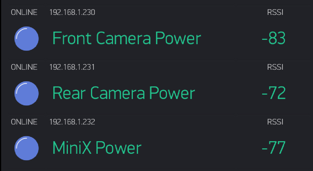
My system is not really close from router wifi, but without OTA code works correctly.
I have another NodeMCU to test, and instead of making the method that send solar panel data, I use a test method that send sum of number. If I stay near my router wifi, my test system works correctly and I can load new code by OTA. But If I walk away and I approach the area where I have the solar panel, NodeMcu disconnect and riconnect and I can’t load new code by OTA.
Why all this???
my code is this, thank you
#include <Blynk.h>
#include <ESP8266mDNS.h>
#include <WiFiUdp.h>
#include <ArduinoOTA.h>

#include <Wire.h>
#include <Adafruit_INA219.h>
#define BLYNK_PRINT Serial

#include <ESP8266WiFi.h>
#include <BlynkSimpleEsp8266.h>

char auth[] = "******";
//char auth[] = "*****";  //  TOKEN DI PROVA

Adafruit_INA219 ina219;

char ssid[] = "ERRICIOFFI2.4";
char pass[] = "lunasissy";

//char ssid[] = "Linkem_0EC983";
//char pass[] = "bjig3vug";

//char ssid[] = "FERRIDEA";
//char pass[] = "possochiedere?";

float shuntvoltage = 0;
float busvoltage = 0;
float current_mA = 0;
float loadvoltage = 0;
float power_mW = 0;
float energy = 0;
float current_h = 0;
float current_day = 0;

unsigned long previousMillis = 0;
unsigned long interval = 100;
unsigned long currentMillis = 0;


#define relayFaretto10WD4 D4
#define relayMadonnaD5 D5
#define greenLEDD7 D7
#define redLEDD8 D8

#define buttonFaretto10W V0  // >> su D4
#define buttonMadonna V1     // >> su D5
#define timerFaretto V2
#define timerMadonna V3
#define correnteIstantanea V4
#define potenzaIstantanea V5
#define energiaTotale V6
#define correnteTotale V7
#define correnteTotaleDay V8
#define correnteTotaleDayGraph V9

boolean isFirstConnect = true;
boolean isConnesso;
boolean canSendCurrentDay = false;

BlynkTimer timer;


void setup(void) {

  Serial.begin(115200);

  Blynk.begin(auth, ssid, pass);
 // Blynk.config(auth);
  //Blynk.connectWiFi(ssid, pass);

  ArduinoOTA.begin();  // For OTA

  ////////////////////////////////
  ina219.begin();


  pinMode(greenLEDD7, OUTPUT);
  pinMode(redLEDD8, OUTPUT);
  pinMode(relayFaretto10WD4, OUTPUT);
  pinMode(relayMadonnaD5, OUTPUT);

  digitalWrite(relayFaretto10WD4, LOW);
  digitalWrite(relayMadonnaD5, LOW);

  // Setup a function to be called every second
  timer.setInterval(1000L, letturaPannelloProva);   //// TEST METHOD
  timer.setInterval(1500L, sendInaValues);
  timer.setInterval(3000L, controllaConnessione);

}


void loop(void){

  timer.run(); // Initiates BlynkTimer
  ArduinoOTA.handle();
  Blynk.run();

}


void letturaPannello() {

  if(!isFirstConnect){
    shuntvoltage = ina219.getShuntVoltage_mV();
    busvoltage = ina219.getBusVoltage_V();
    current_mA = (abs(ina219.getCurrent_mA())/1000);
    power_mW = ina219.getPower_mW()/1000;
    loadvoltage = busvoltage + (shuntvoltage / 1000);
    current_h = (current_h + current_mA / 3600)/1000;   // conteggio corrente totale
    current_day = (current_day + current_mA / 3600)/1000;   // conteggio corrente giornaliero
    energy = (energy + loadvoltage * current_mA / 3600)/1000;  // conteggio corrente energia
  }

}


void controllaConnessione(){

  if(Blynk.connected()){

    digitalWrite(greenLEDD7, HIGH);
    digitalWrite(redLEDD8, LOW);
    isConnesso = true;

  }else{

    digitalWrite(greenLEDD7, LOW);
    digitalWrite(redLEDD8, HIGH);
    isConnesso = false;
    Blynk.connect();
    //Blynk.begin(auth, ssid, pass);

  }

}


void sendInaValues(){

  Blynk.virtualWrite(correnteIstantanea, current_mA);  // V4
  Blynk.virtualWrite(potenzaIstantanea, power_mW);   // V5
  Blynk.virtualWrite(energiaTotale, energy);  // V6
  Blynk.virtualWrite(correnteTotale, current_h);   // V7
  Blynk.virtualWrite(correnteTotaleDay, current_day);  // V8
  if(canSendCurrentDay){ // ALLO STOP DEL TIMER FARETTO
    Blynk.virtualWrite(correnteTotaleDayGraph, current_day);  // MANDO IL VALORE TOTALE DELLA CORRENTE PRODOTTA
    current_day = 0;
    canSendCurrentDay = false;
  }

}


BLYNK_WRITE(buttonFaretto10W){  //controllo VIRTUAL Button Faretto   V0  >> D4

  if(param.asInt()==1){
    digitalWrite(relayFaretto10WD4, HIGH);  // START RELAY FARETTO
  }else{
    digitalWrite(relayFaretto10WD4, LOW);   // STOP RELAY FARETTO
    canSendCurrentDay = true;
  }
}


BLYNK_WRITE(buttonMadonna){  //controllo VIRTUAL Button Madonna    V1  >> D5

  if(param.asInt()==1){
    digitalWrite(relayMadonnaD5, HIGH);  // START RELAY MADONNA
  }else{
    digitalWrite(relayMadonnaD5, LOW);   // STOP RELAY MADONNA
  }
}


BLYNK_WRITE(timerFaretto){  // timer V2 >>> buttonFaretto V0

  if (param.asInt() == 1) {
    Blynk.virtualWrite(buttonFaretto10W, 1); // button set to ON from timer
    //digitalWrite(relayFaretto10WD4, HIGH);
  }
  else{
    Blynk.virtualWrite(buttonFaretto10W, 0); // button set to OFF from timer
    //digitalWrite(relayFaretto10WD4, LOW);
  }
}


BLYNK_WRITE(timerMadonna){  // timer V3 >>> buttonFaretto V1

  if (param.asInt() == 1) {
    Blynk.virtualWrite(buttonMadonna, 1); // button set to ON from timer
    //digitalWrite(relayMadonnaD5, HIGH);
  }
  else{
    Blynk.virtualWrite(buttonMadonna, 0); // button set to OFF from timer
    //digitalWrite(relayMadonnaD5, LOW);
  }
}


//////////////////     S Y N C  ///////////////////////////////////
BLYNK_CONNECTED() {
  if (isFirstConnect) {
    Blynk.syncVirtual(energiaTotale);     // V6
    Blynk.syncVirtual(correnteTotale);    // V7
    Blynk.syncVirtual(correnteTotaleDay); // V8
    isFirstConnect = false;
  }
  isConnesso = true;
}


BLYNK_WRITE(energiaTotale){
  energy = param[0].asFloat();
}

BLYNK_WRITE(correnteTotale){
  current_h = param[0].asFloat();
}

BLYNK_WRITE(correnteTotaleDay){
  current_day = param[0].asFloat();
}


void stampaValori(){
  Serial.print("Bus Voltage:   "); Serial.print(busvoltage); Serial.println(" V");
  Serial.print("Shunt Voltage: "); Serial.print(shuntvoltage); Serial.println(" mV");
  Serial.print("Load Voltage:  "); Serial.print(loadvoltage); Serial.println(" V");
  Serial.print("Current:       "); Serial.print(current_mA); Serial.println(" mA");
  Serial.print("Power:         "); Serial.print(power_mW); Serial.println(" mW");
  Serial.print("Energia:         "); Serial.print(energy); Serial.println(" mWh");
  Serial.println("");
}


void letturaPannelloProva() {

   if(!isFirstConnect){
      shuntvoltage = ina219.getShuntVoltage_mV();
      busvoltage = ina219.getBusVoltage_V();
      current_mA = current_mA+0.5;
      power_mW = power_mW+0.5;
      loadvoltage = busvoltage + (shuntvoltage / 1000)+0.5;
      current_h = current_h+0.5;   // conteggio corrente totale
      current_day = current_day + 0.5;   // conteggio corrente giornaliero
      energy = energy + 0.5;  // conteggio corrente energia
   }


}