That’s correct!
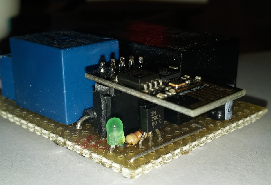
For this setup I’m using the 2N3904
You are generally correct ![]() … Usually 5v, 12v or even 24v coils, but almost all with 5v logic triggering, that may or may not be 3.3v compliant (cheap design may skimp on that). Industrial relay logic gets into 5-24v triggering compliance, but that’s another issue
… Usually 5v, 12v or even 24v coils, but almost all with 5v logic triggering, that may or may not be 3.3v compliant (cheap design may skimp on that). Industrial relay logic gets into 5-24v triggering compliance, but that’s another issue ![]()
@Costas is correct, don’t bother until you know what you are getting into… LL Converters are necessary when sharing data lines between 3.3v and 5v devices, but not critical when triggering relays.
A relay will either trigger on 3.3v or it won’t… most will as the mid-point (between OFF and ON) in a typical 5v logic signal is 2v-2.5v, but some cheap relays are just cheap ![]()
I 2nd that !! ![]()
Has this topic been solved yet? it seems to have migrated into an “ask @Costas” thread… HEY! Now that is a great name for a Category Label ![]()
Can someone explain me why when i trigger with Timer Wiget for example
Start 20:00:00, Stop 20:00:02 the signal goes HIGH but do not go back by Stop at 20:00:02.
In the description i can read that the stop signal is will be LOW.
BLYNK_WRITE(V6)
{
digitalWrite(13, HIGH); // GPIO13
}
It’s because your virtual pin V6 has the value low/High according to your timer but you never use it in your digital write.
Should be something like this
digitalWrite(13, param.asInt());
The docs would probably be a good place @Tom that’s why time and trouble was taken to create them.
Any term you are not sure about, copy the word from the screen, go to docs, ctrl F and paste the word.
Hi, if i want to use two devices in one blynk app projects, is then a “Bride” necessary or is it enough if you use different pins (physical and virtual)?
Token for both hardware devices is the same.