I do not know much about this sensor (or what the above formula is for), but you may need to increase 1024 to 2048 as the ADS1015 is a 12 bit ADC and the esp/arduino have a 10 bit ADC
@Toro_Blanco ok i understand but in my code I have 2 sensors each 3.3v …i set the gain corectly ???
1 soil moisture 3.3v
1 UV sensor 3.3.v
ads.setGain(GAIN_TWO); // 2x gain +/- 2.048V 1 bit = 1mV 0.0625mV
the gain you are using is for a maximum sensor input voltage of 2.048V. This is below 3.3V. You need to increase it.
float outputVoltage = 5.0 * uvLevel / 1024;
I Changed
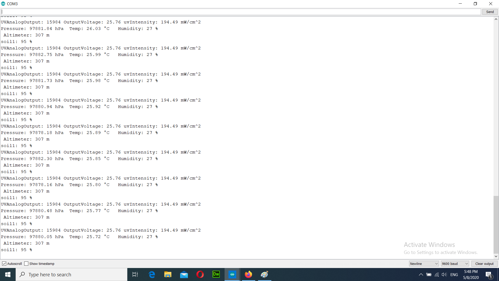
float outputVoltage = 3.3 * uvLevel / 1024;
Do you have any way to check the accuracy of the UV sensor? How do you know the values you are getting are correct?
Soil moisture is easy, as it is a bit subjective. You can “feel” when it is dry, and time to water.
1024 is the resolution of the 10 bit ADC used in the arduino and ESP. The ADS1015 has a 12 bit ADC which has a resolution of 4096, but since the ADS splits this range over plus and minus, the plus side has a 2048 resolution. The formula is for converting the analog reading back into a voltage. You have to use the correct resolution or else you won’t get the correct value.
float outputVoltage = 3.3 * uvLevel / 2048;
1 Like
Yes this is another problem. I don’t understand what values UV reads …and if it is correct my values
and what gain are you using?
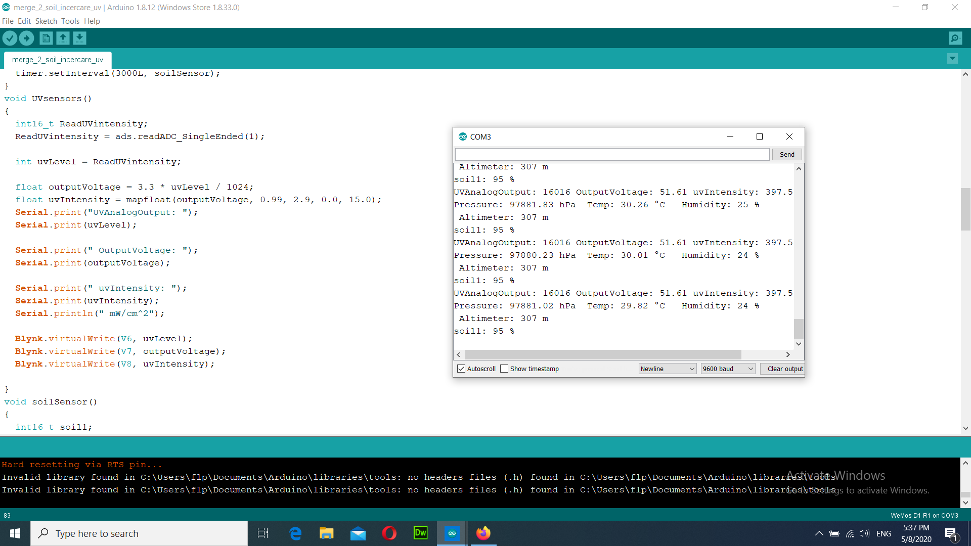
The value being read by the ADS seems way high. It should not exceed 2048.
The same gain … i don’t understand so much but i will research … another problem ist soil sensor because i have sometimes value with -1023%
i can’t find the formula how i can read the UV sensor…something is wrong in my code…
It sounds like you didn’t take this advice, but the advice still stands. Take a step back and tackle one issue at a time.
Pete.
This seams like a fairly good tutorial on the ML8511. It also includes a neat trick to make the ADC more accurate with varying input voltages. Give it a read.
https://learn.sparkfun.com/tutorials/ml8511-uv-sensor-hookup-guide/all
how ???
does your UV sensor have 4 pins or 3? Can you share a link to the exact sensor you have?
i have 5 pins but i have connect only 3
vcc /3.3
out A1 from ads1115
gnd / gnd
look like this https://www.ebay.de/i/263558181698?chn=ps&norover=1&mkevt=1&mkrid=707-134425-41852-0&mkcid=2&itemid=263558181698&targetid=860140269485&device=c&mktype=pla&googleloc=9060719&poi=&campaignid=1669295905&mkgroupid=88815387825&rlsatarget=pla-860140269485&abcId=1139676&merchantid=138392580&gclid=Cj0KCQjwhtT1BRCiARIsAGlY51KwETeJrWzmXO4cy65s9Kc6BfC3G4Ntxw1zr5CJJ5Ze_kNfPQqTkYEaAhhgEALw_wcB
Is there any reason why you’ve chosen a UV sensor with an analogue output rather than I2C ?
Pete.
how ? i dont have free pins on my board…
when i read the sensor without ads1115 i have the normal value…
In that case you won’t be able to use the ADS1015 multiplexor as this requires I2C as well.
Pete.
yes i have 2 I2C of my board …one i connect ads1115 and another one i have connected BME280 sensor …