You are wrong ;). You can send any number you want. For example, I use it to address a PWM dimmable LED. In theory I could add a webhook to send the number I’m speaking.
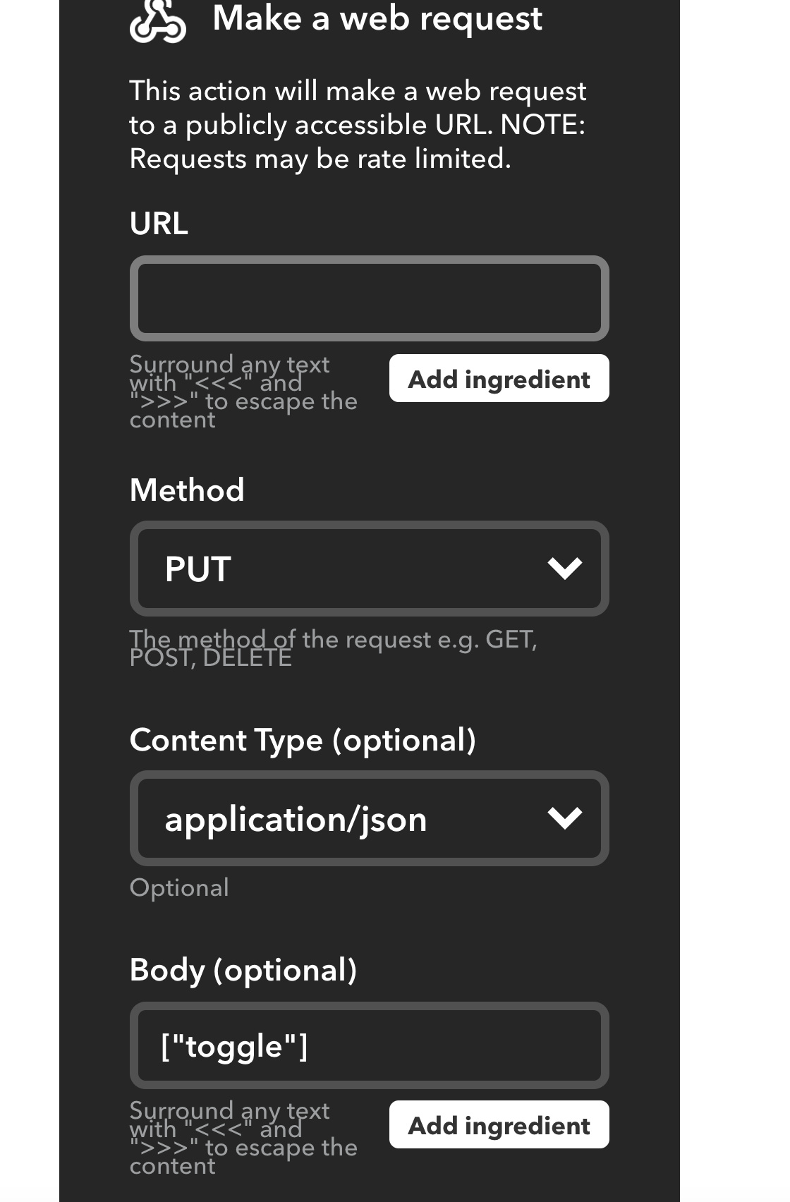
Have you tried sending [“0”] or [“1”] instead of toggle? Because I don’t see anything in your code to reflect that. Besides, a digital pin can only be 1 or 0.
Write a Blynk function that is called whenever your voice command happens… the function will simply toggle the relays current pin state to its opposing state.
BLYNK_WRITE(Vx) {  // Relay toggle function processes the following command regardless of the state of the calling vPin
digitalWrite(RelayGPIOpin, !digitalRead(RelayGPIOpin)); // Go HIGH if LOW, go LOW if HIGH
}
You may want to add in some minor timer and flag to keep this from rapidly flip flopping if this function somehow gets rapidly called (e.g. as would happen if using a momentary Button Widget to call this function).
You could also make it so that your voice command always triggers a HIGH, and make this function only trigger on HIGH, but then after flipping the relay, reset the vPin to LOW.
ive tried to learn more about the project which i put on the back burner and have gotten to here
my understanding is that i will call for a virtual pin via iftt to high or “1” then the code will take that and decide what the state of the pin is and change it accordingly ?
here is the code i have attempted (which doesnt work )
#define BLYNK_PRINT Serial


#include <ESP8266WiFi.h>
#include <BlynkSimpleEsp8266.h>

// You should get Auth Token in the Blynk App.
// Go to the Project Settings (nut icon).
char auth[] = "xxxxxxxxxxx";

// Your WiFi credentials.
// Set password to "" for open networks.
char ssid[] = "xxxxxxxh";
char pass[] = "xxxxx";

void setup()
{


 // Debug console
 Serial.begin(9600);

 Blynk.begin(auth, ssid, pass);
 // You can also specify server:
 //Blynk.begin(auth, ssid, pass, "blynk-cloud.com", 84xx);
 //Blynk.begin(auth, ssid, pass, IPAddress(192,1xx,1,100), 84xx42);

 int outputPin = 14;

}

void loop()
{
 Blynk.run();

 BLYNK_WRITE(V1) ;  // Relay toggle function processes the following command regardless of the state of the calling vPin
 digitalWrite(outputPin, !digitalRead(outputPin)); // Go HIGH if LOW, go LOW if HIGH

}
so my understanding of what you have written ( as im a complete noob) is
blynk_write(vx) is the virtual pin my iftt will call for
i will need to assign a gpio pin and define it as (Relay GPIOpin)
after looking around i have found other people doing similar thing to what i am trying to achieve but using current/voltage sensing, that is a option but not required as i can use a voice command to just change the state of a two position relay using the voice command “hallway lights”
i am basically creating a three way switch with the "intermediate switch " being under the control of the google assistant and the node mcu
/*************************************************************
  Download latest Blynk library here:
    https://github.com/blynkkk/blynk-library/releases/latest

  Blynk is a platform with iOS and Android apps to control
  Arduino, Raspberry Pi and the likes over the Internet.
  You can easily build graphic interfaces for all your
  projects by simply dragging and dropping widgets.

    Downloads, docs, tutorials: http://www.blynk.cc
    Sketch generator:           http://examples.blynk.cc
    Blynk community:            http://community.blynk.cc
    Follow us:                  http://www.fb.com/blynkapp
                                http://twitter.com/blynk_app

  Blynk library is licensed under MIT license
  This example code is in public domain.

 *************************************************************

  This example shows how value can be pushed from Arduino to
  the Blynk App.

  NOTE:
  BlynkTimer provides SimpleTimer functionality:
    http://playground.arduino.cc/Code/SimpleTimer

  App project setup:
    Value Display widget attached to Virtual Pin V5
 *************************************************************/

/* Comment this out to disable prints and save space */
#define BLYNK_PRINT Serial


#include <ESP8266WiFi.h>
#include <BlynkSimpleEsp8266.h>

// You should get Auth Token in the Blynk App.
// Go to the Project Settings (nut icon).
char auth[] = "xxxxxx";

// Your WiFi credentials.
// Set password to "" for open networks.
char ssid[] = "txxxdxxxxxixxx";
char pass[] = "xxxxx";

BlynkTimer timer;

// This function sends Arduino's up time every second to Virtual Pin (5).
// In the app, Widget's reading frequency should be set to PUSH. This means
// that you define how often to send data to Blynk App.
void myTimerEvent()
{
  // You can send any value at any time.
  // Please don't send more that 10 values per second.
  Blynk.virtualWrite(V5, millis() / 1000);
}

void setup()
{
  // Debug console
  Serial.begin(9600);

  Blynk.begin(auth, ssid, pass);
  // You can also specify server:
  //Blynk.begin(auth, ssid, pass, "blynk-cloud.com", 8442);
  //Blynk.begin(auth, ssid, pass, IPAddress(192,168,1,100), 8442);

  // Setup a function to be called every second
  timer.setInterval(1000L, myTimerEvent);
}

void loop()
{
  Blynk.run();
  timer.run(); // Initiates BlynkTimer
  BLYNK_WRITE(V1) ;  // Relay toggle function processes the following command regardless of the state of the calling vPin
  digitalWrite(14, !digitalRead(14));  // Using GPIO14 (D5) Go HIGH if LOW, go LOW if HIGH


}