Help with ESP-01 relay module (Possibly Non Blynk Related)

I’m trying to use a esp-01 with relay module to do stuff. Right now it will just turn a led on and off on my bread board but if I get it working then I will adapt it to do other things. Right now I cant get the Blynk app to control the relay.

Some common troubleshooting questions:
What board and module?
-https://www.aliexpress.com/item/Elecrow-ESP8266-ESP-01S-Relay-Module-5-Minutes-IoT-Project-DIY-Kit-WiFi-Internet-Controlled-Relays/32817065299.html

The app is setup with ESP8266 board.

What pin?
-according to everything I can find the GPIO2 pin is the one that controls the relay, i have confirmed with a 3.3v+ directly wired to the pin.

Code?
-I can post the code if needed but I was using the example for esp8266 wifi in the blynk library.

The board boots, and the Blynk app connects to the board, but the buttons dont work. My button is a digital gp2 button switching between 0 and 1.

Any help will be greatly appreciated. If the answer is already out there I’m sorry I searched and searched and i couldn’t find anything with this board and this module.

P.S. I know this can work i have seen it in person. Unfortunately I have no way of contacting the person who showed it to me.

/*************************************************************
  Download latest Blynk library here:
    https://github.com/blynkkk/blynk-library/releases/latest

  Blynk is a platform with iOS and Android apps to control
  Arduino, Raspberry Pi and the likes over the Internet.
  You can easily build graphic interfaces for all your
  projects by simply dragging and dropping widgets.

    Downloads, docs, tutorials: http://www.blynk.cc
    Sketch generator:           http://examples.blynk.cc
    Blynk community:            http://community.blynk.cc
    Follow us:                  http://www.fb.com/blynkapp
                                http://twitter.com/blynk_app

  Blynk library is licensed under MIT license
  This example code is in public domain.

 *************************************************************
  This example runs directly on ESP8266 chip.

  Note: This requires ESP8266 support package:
    https://github.com/esp8266/Arduino

  Please be sure to select the right ESP8266 module
  in the Tools -> Board menu!

  Change WiFi ssid, pass, and Blynk auth token to run :)
  Feel free to apply it to any other example. It's simple!
 *************************************************************/

/* Comment this out to disable prints and save space */
#define BLYNK_PRINT Serial


#include <ESP8266WiFi.h>
#include <BlynkSimpleEsp8266.h>

// You should get Auth Token in the Blynk App.
// Go to the Project Settings (nut icon).
char auth[] = "xxxx";

// Your WiFi credentials.
// Set password to "" for open networks.
char ssid[] = "xxxx";
char pass[] = "xxxx";

void setup()
{
  // Debug console
  Serial.begin(9600);

  Blynk.begin(auth, ssid, pass);
}

void loop()
{
  Blynk.run();
}

This is not really a Blynk related question.

Depending on the ESP-01 board you have GPIO2 is also connected to the internal LED, so if you are properly connected to Blynk, then you should also see that LED turn on and OFF (NOTE that depending on how you hook up the relay, the button ON, may be OFF on the relay and visa versa.

Also, these little boards only supply 3.3v and very low current, so probably not enough current to properly energize a relay coil (Since most are 5v) So test your pin control with an LED/resistor instead.

Thank you for your response. I’ll test the pin with a led and get back to you.
As for the board firing the relay, the relay module I have is made for the esp-01 to control (see link above) and I have seen it work with the relay turning a lamp on and off. I know the voltage and current are low but the module seems to be made to handle it.
Also, you say this is not blynk related and you may be right. I posted this on arduino forums as well, just casting my net wide as I am having trouble finding info on this thing.
Thanks again for your patience.

1 Like

But it is still rated for 5V external power… As shown on the relay and even stated in the site details

“… just supply a DC5V power, then you can control it.”

image

Are you sure you have the sketch properly uploaded and that the App is connected to it?

Have you tried the directions when you first got it? Did it work with the firmware they clearly had installed?

If it doesn’t work, refer back to the supplier.

1 Like

OK yes I have it supplied with 5v. I forgot to mention that before. I have a power supply hooked through my breadboard to the module. I also have the pull up resistors connected so that the esp-01 will boot in “run-mode”.
I have not tried it with that app only blynk (board and module are hand me down so I haven’t seen what you showed me before).
Code is uploaded on the board correctly, I’ve tried a few times.

Also sorry for the confusion. I didn’t buy this module though that link so it didn’t come with that app or firm ware or any of that. The link is just for visual to see the hardware. This board I have came with the at firmware that is standard but in have since flashed the example sketch above to it.
Thanks again for the help brother, I’m about to scrap this project and just use it as a shield with the uno. I’ve already made that work before plus I control more relays as well.

That is an option… but they can easily be used as standalone as well

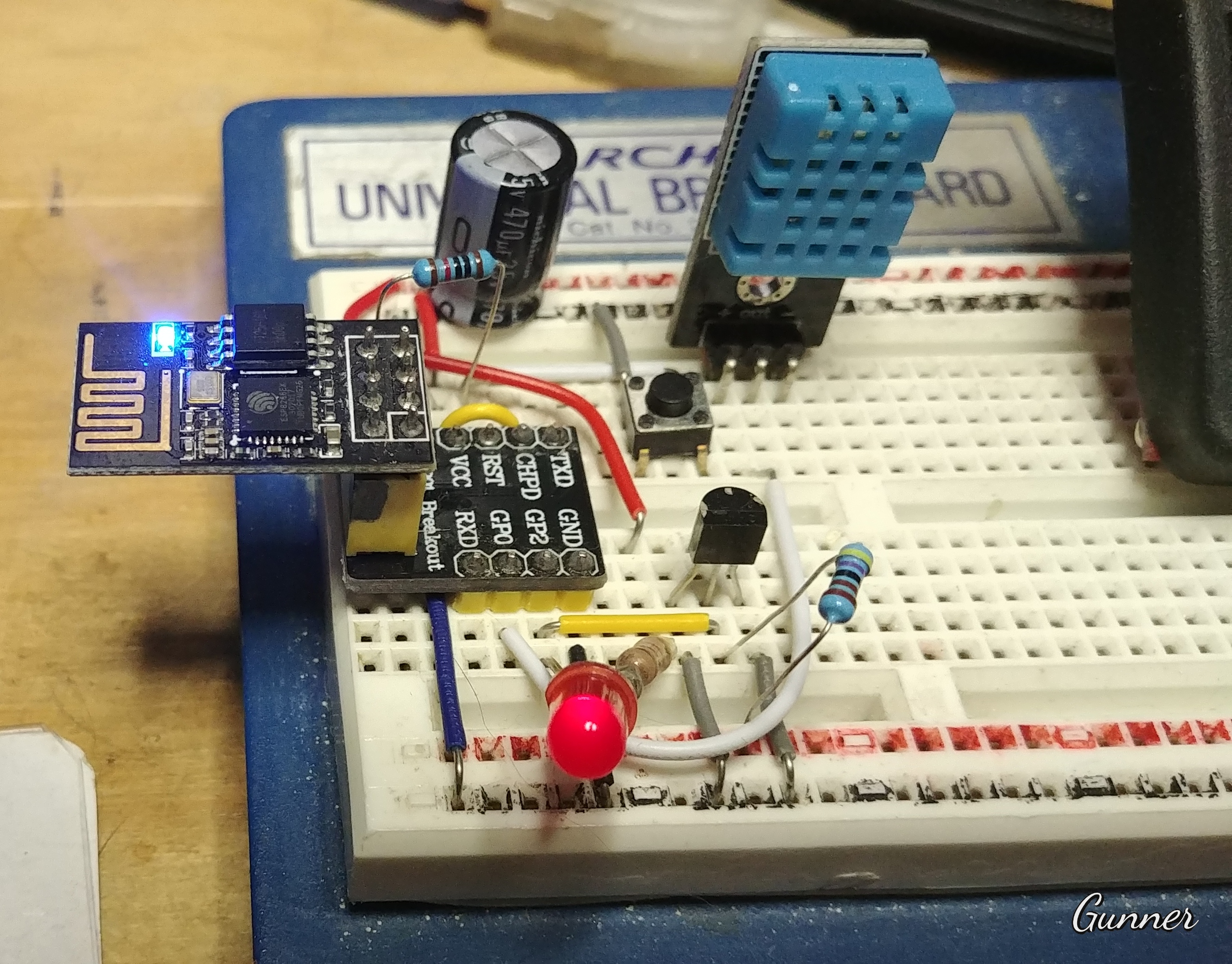
I have one running a DHT11 & DS18B20, (and I even managed an LED on GPIO2, the same pin as the DS18B20 :stuck_out_tongue_winking_eye: with a direct pin controlled button as discussed above. Since the DS18B20 is called on a timer, the LED doesn’t actually interfere)

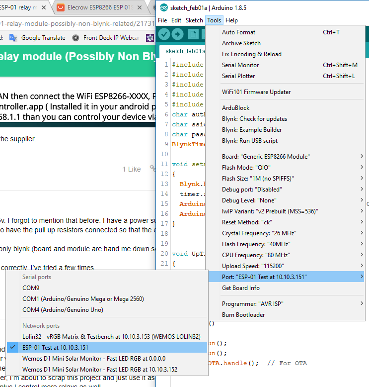
Well, if you are able to flash sketches via the Arduino IDE, then you should have no problem getting it to work with Blynk. Although due the hassle of always hooking it up to a TTL-USB adapter for said flashing, I highly recommend you use a sketch setup for OTA each time, that way you can keep reprogramming it via OTA.

#include <ESP8266WiFi.h>
#include <BlynkSimpleEsp8266.h>
#include <ESP8266mDNS.h>  // For OTA
#include <WiFiUdp.h>  // For OTA
#include <ArduinoOTA.h>  // For OTA
char auth[] = "xxxxxxxxxx";
char ssid[] = "xxxxxxxxxx";
char pass[] = "xxxxxxxxxx";
BlynkTimer timer;

void setup()
{
  Blynk.begin(auth, ssid, pass);
  timer.setInterval(1000L, UpTime);
  ArduinoOTA.setHostname("ESP-01 Test");  // For OTA
  ArduinoOTA.begin();  // For OTA
}


void UpTime()
{
  Blynk.virtualWrite(V0, millis() / 1000);  // Display Widget on V0 for UpTime in Seconds (use / 60000 for minutes)
  Blynk.virtualWrite(V1, WiFi.RSSI());  // Display Widget on V1 for RSSI strength
}


void loop()
{
  Blynk.run();
  timer.run();
  ArduinoOTA.handle();  // For OTA
}

2 Likes

Thank you again Gunner. You have been a wealth of knowledge on the topic. The problem is with me and the board. More research needed. I am brand new.

Definitely gonna do this. Never even thought to try (again brand new)