I came across these Wi-Fi LED Controllers, for RGB LED strips on eBay:
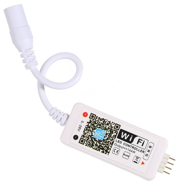
Mine was GBP £5.40 because I ordered it from a UK supplier, but if you’re happy to wait for them to arrive from China you can buy the same item cheaper on eBay, AliExpress, Banggood etc.
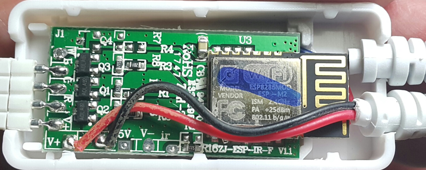
They also make a slightly more expensive version that has an IR remote as well as Wi-Fi app control, but I wasn’t interested in that functionality so went for the cheaper version. If you flash the code below onto the IR version then the IR remote won’t work (but I’m guessing that the Blynk functionality should work okay).
As usual, I didn’t brother trying the manufacturer’s app and instead went straight for popping the case apart and seeing what was inside.
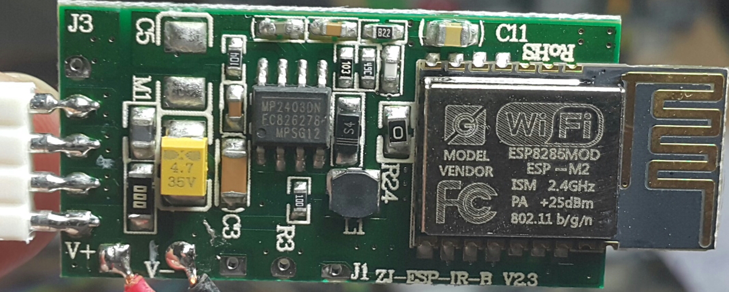
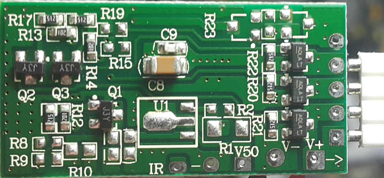
As I’d hoped, it was an ESP chip (an ESP8285 in this case) and the manufacturer has thoughtfully made it fairly easy to identify and connect to the pins that are needed to flash your own firmware.
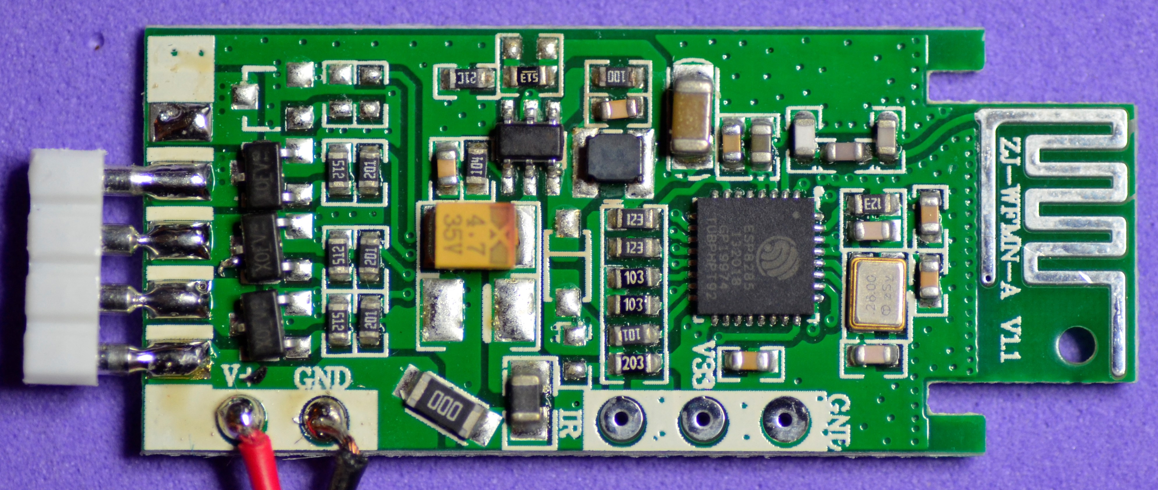
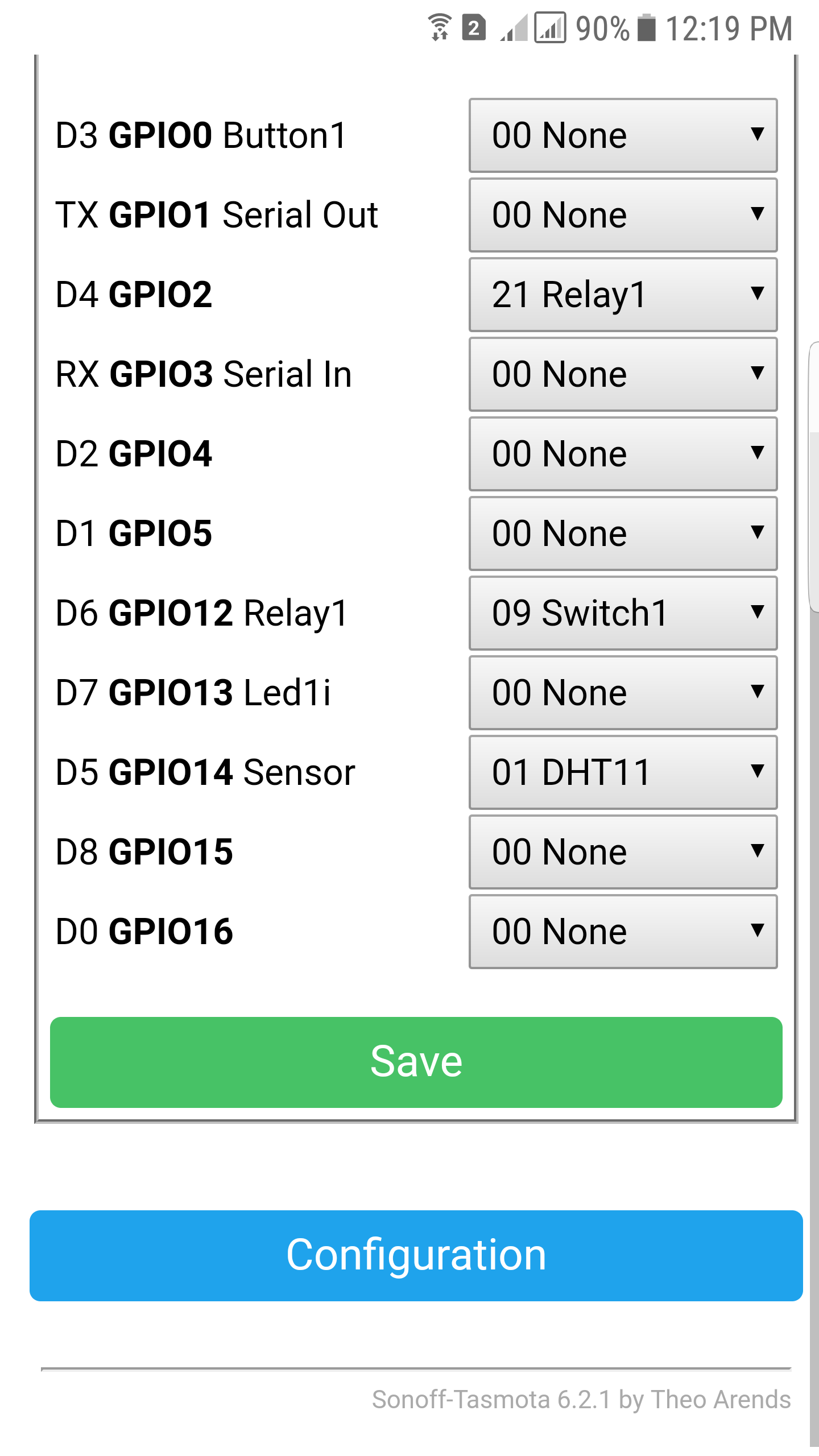
A bit of time spent tracing the tracks and referring to the Expressif data sheet for the ESP8285 revealed that GPIOs 5, 12 and 13 are used to control the R, G and B channels.
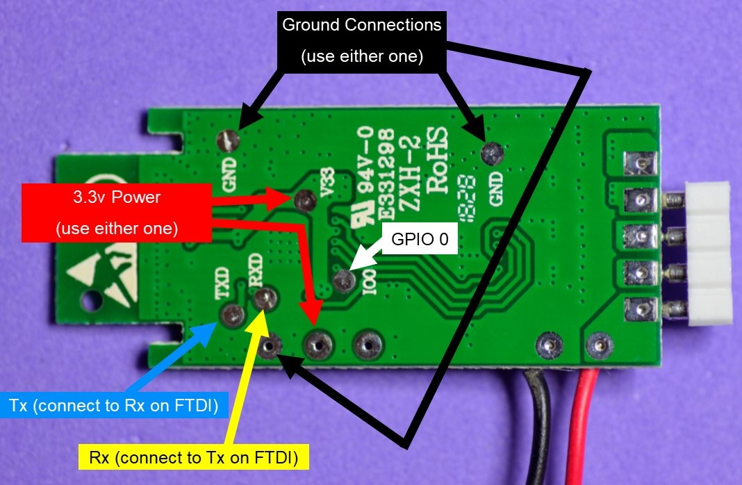
I soldered some temporary wires on to the board and connected-up a USB to Serial FTDI interface (set to 3.3v), temporarily shorted GPIO0 to ground whilst plugging the FTDI into my PC then flashed some test firmware which worked first time 
Here’s the basic Blynk code:
// Blynk + OTA Code for "Wi-Fi LED Controller" by Pete Kniight
// Arduino IDE Upload Settings
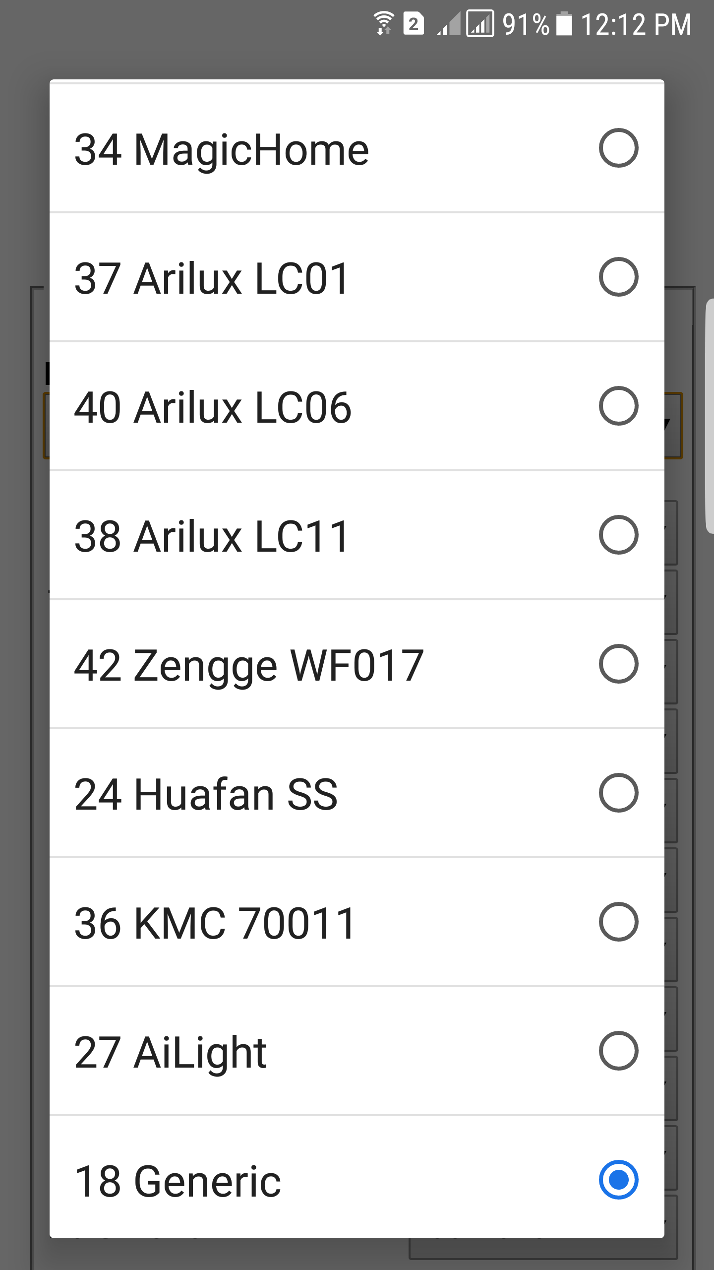
// Board: "Generic ESP8285 Module"
// Upload Speed: "115200"
// CPU Frequency: "80MHz"
// Crystal Frequency "26 MHz"
// Flash Size: "1M (No SPIFFS)"
// Reset Method: "ck"
// IwIP Variant: "v2 Higher Babdwidth"
// Blynk App Project Setup:
// Add a Button widget connected to Virtual Pin V1, set to Switch mode
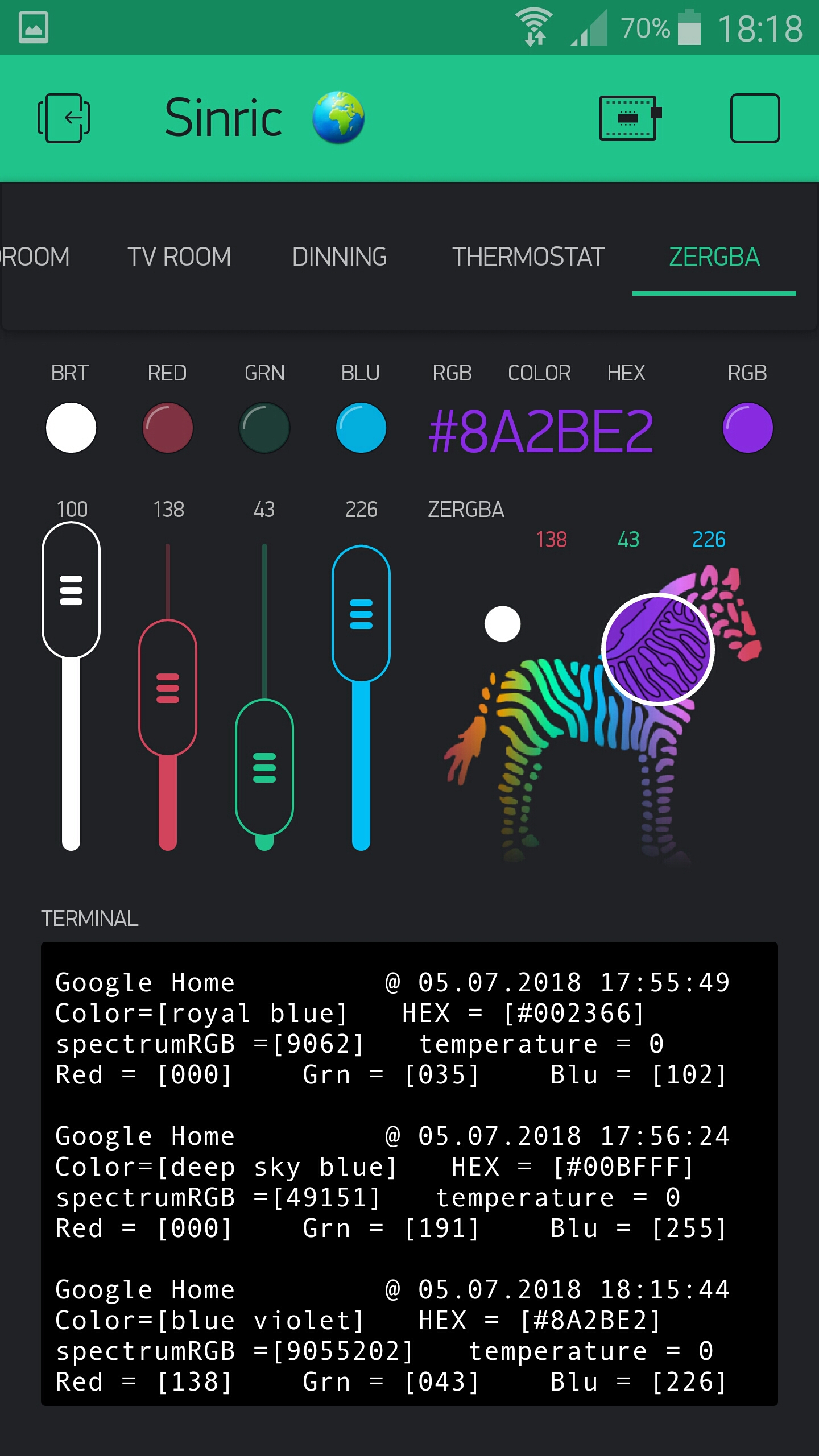
// Add a ZeRGBa widget connected to Virtual Pin V2, set to Merge mode and values of 0-1023 for each channel
#include <ArduinoOTA.h>
#include <ESP8266WiFi.h>
#include <BlynkSimpleEsp8266.h>
char auth[] = "REDACTED";
char ssid[] = "REDACTED";
char pass[] = "REDACTED";
char OTAhost[] = "RGB Controller";
#define REDPIN 5
#define GREENPIN 12
#define BLUEPIN 13
int Power = 0; // We want the power to be Off at startup
void setup()
{
pinMode(REDPIN, OUTPUT);
pinMode(GREENPIN, OUTPUT);
pinMode(BLUEPIN, OUTPUT);
WiFi.mode(WIFI_STA);
Blynk.begin(auth, ssid, pass);
while (Blynk.connect() == false) {} // Don't proceed until we're connected to WiFi/Blynk
Blynk.virtualWrite(V4, 0); // Turn the button widget Off on the app, to match the power off status
ArduinoOTA.onError([](ota_error_t error) { ESP.restart(); });
ArduinoOTA.setHostname(OTAhost);
ArduinoOTA.begin();
}
void loop()
{
Blynk.run();
ArduinoOTA.handle();
}
BLYNK_WRITE(V1) // Button assigned to V1
{
Power = param.asInt();
if (Power == 0) // If the button widget is set to Off then turn the LEDs off
{
analogWrite(REDPIN, 0);
analogWrite(GREENPIN, 0);
analogWrite(BLUEPIN, 0);
}
else
{
Blynk.syncVirtual(V2); // If the button widget is On, force a BLYNK_WRITE(V2) to set the LEDs to the ZeRGBa values
}
}
BLYNK_WRITE(V2) // zeRGBa assigned to V2
{
if (Power == 1) // Only apply the ZeRGBa changes if the power is On
{
// get the RED channel value and update the corresponding GPIO Pin
int r = param[0].asInt();
analogWrite(REDPIN, r);
// get the GREEN channel value and update the corresponding GPIO Pin
int g = param[1].asInt();
analogWrite(GREENPIN, g);
// get the BLUE channel value and update the corresponding GPIO Pin
int b = param[2].asInt();
analogWrite(BLUEPIN, b);
}
}
There’s obviously no re-connection routine included in this simple code, and it’s designed so that the LED strip will be off when the controller is powered-up. Changes to the ZeRGBa widget while the power button widget is off will have no effect until the power button widget is turned on.
OTA routines are included so that the temporary wires needed to flash the initial code can be removed and future updates done via standard OTA.
Enjoy!
Pete.


