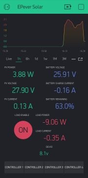
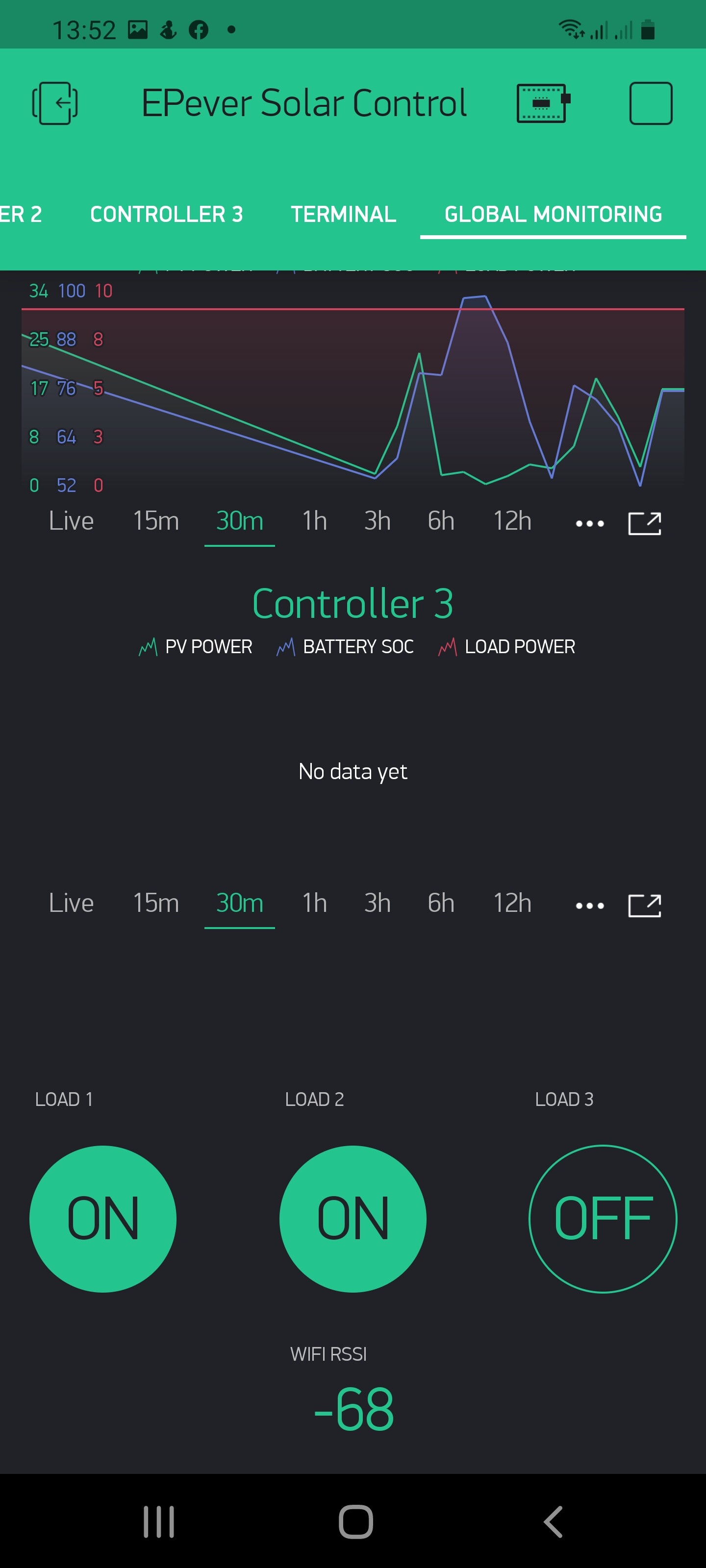
I’ve reached that crucial point where it all appears to be working as it should. I’m sure it can be refined and made to work better, but for the moment, I shall wallow in the fact it works.
I couldn’t have done it without Pete’s help so a huge thank you to him.
This is my largest Blynk project and used about 30,000 Blynk Energy so if you don’t have your own Blynk Server you’ll have to spend a few pennies on energy.
CODE:
#include <ArduinoOTA.h>
#include <ESP8266WiFi.h>
#include <BlynkSimpleEsp8266.h> //Blynk support
#include <ModbusMaster.h> //https://github.com/4-20ma/ModbusMaster/
#include "esp_credentials.h" // include WIFI credentials and Blynk auth token credentials
// Attach virtual terminal to Virtual Pin V1
WidgetTerminal terminal(V1);
#define MAX485_DE D1 // On custom PCB these connections are hard-wired as follows...
#define MAX485_RE D2 // DE--> D1 (GPIO5) and RE--> D2 (GPIO4)
int next_controller = 1; // Pointer to indicate which controller (node) will be read next (1, 2 or 3)
// These are the internal registers for the various pieces of data...
// 3100 Registers ....
#define PANEL_VOLTS 0x00 // Address 3100
#define PANEL_AMPS 0x01 // Address 3101
#define PANEL_POWER_L 0x02 // Address 3102
#define PANEL_POWER_H 0x03 // Address 3103
#define BATT_VOLTS 0x04 // Address 3104
#define BATT_AMPS 0x05 // Address 3105
#define BATT_POWER_L 0x06 // Address 3106
#define BATT_POWER_H 0x07 // Address 3107
// 310C Registers...
#define LOAD_VOLTS 0x00 // Address 310C
#define LOAD_AMPS 0x01 // Address 310D
#define LOAD_POWER_L 0x02 // Address 310E
#define LOAD_POWER_H 0x03 // Address 310F
// 3110 Registers...
#define BATT_TEMP 0x00 // Address 3110
#define CONTROL_TEMP 0x01 // Address 3111
// 311A Registers...
#define BATT_SOC 0x00 // Address 311
uint8_t result;
ModbusMaster node; // Define ModbusMaster object...
BlynkTimer timer; // initiate the timer object...
void setup()
{
Blynk.begin(AUTH, WIFI_SSID, WIFI_PASS);
ArduinoOTA.onError([](ota_error_t error) { ESP.restart(); });
ArduinoOTA.setHostname("EPEver_Monitor");
ArduinoOTA.begin();
terminal.clear();
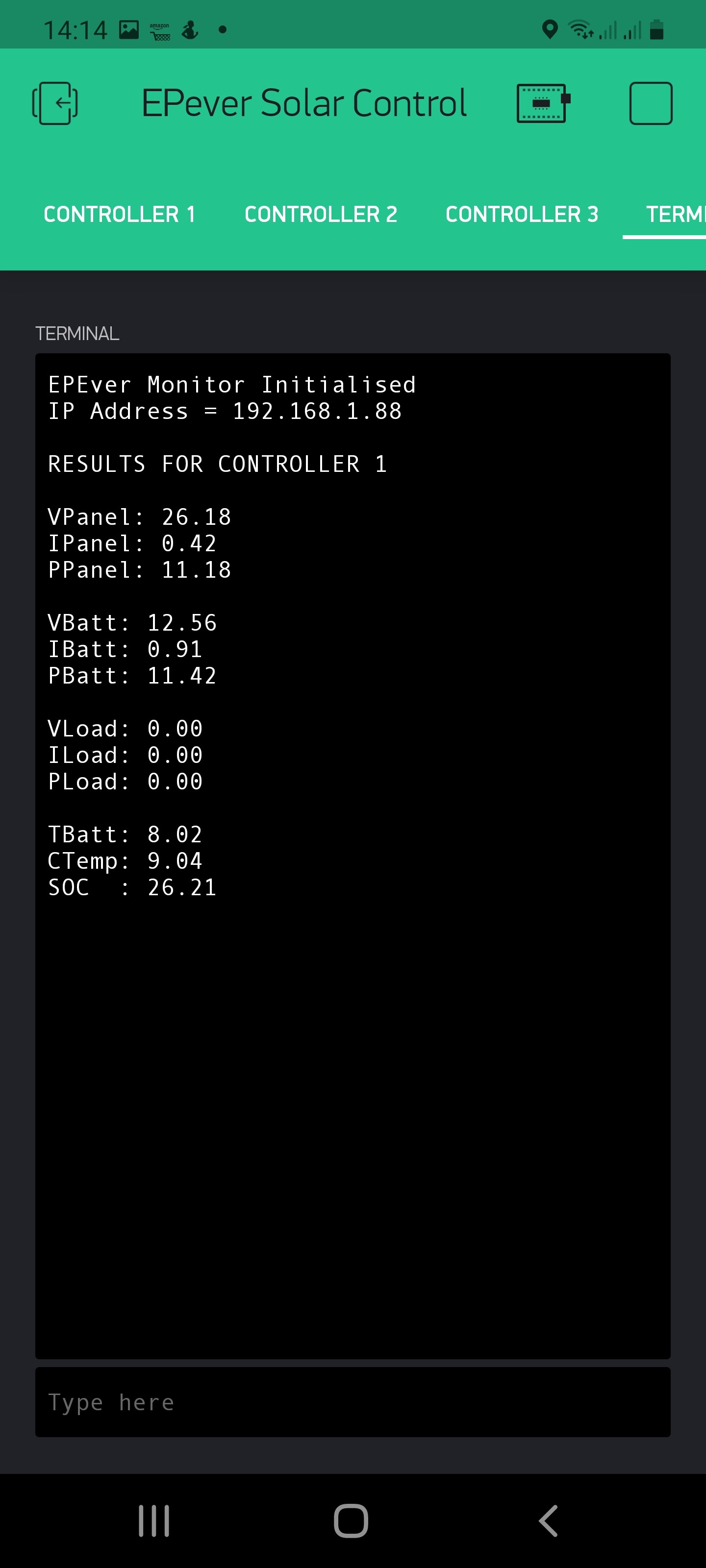
terminal.println("EPEver Monitor Initialised");
terminal.print("IP Address = ");
terminal.println(WiFi.localIP());
terminal.println();
Serial.begin(115200); // Must be 115200 for EPEver devices
pinMode(MAX485_RE, OUTPUT);
pinMode(MAX485_DE, OUTPUT);
// Init in receive mode
digitalWrite(MAX485_RE, 0);
digitalWrite(MAX485_DE, 0);
// Define the callbacks for the nodes.
node.preTransmission(preTransmission);
node.postTransmission(postTransmission);
timer.setInterval(10000, read_controllers_in_sequence);
}
void read_controllers_in_sequence()
{
// This function is called by the timer to read the next controller in the sequence 1, 2 then 3 and back to 1 again...
node.begin(next_controller, Serial);
readMODBUS();
Blynk.virtualWrite(100, WiFi.RSSI());
next_controller = next_controller+1;
if (next_controller > 3)
{
next_controller = 1;
}
}
// The code for reading controllers ...
void readMODBUS()
{
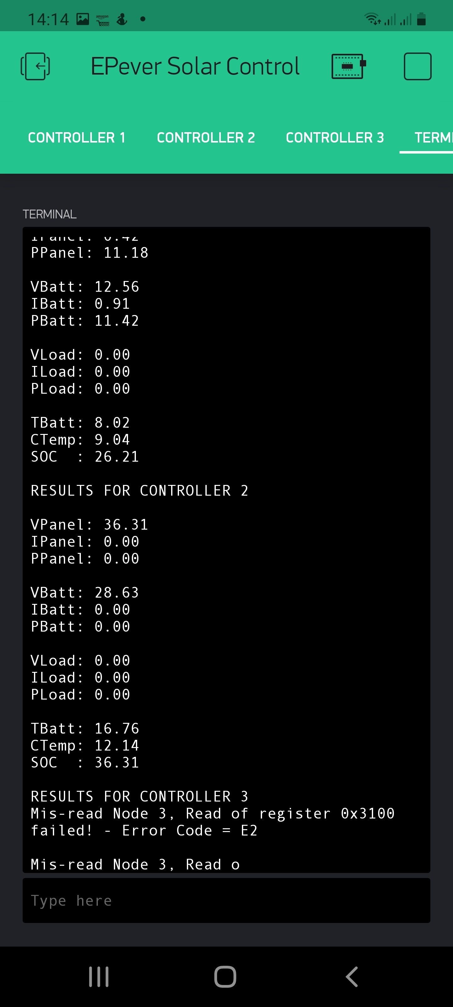
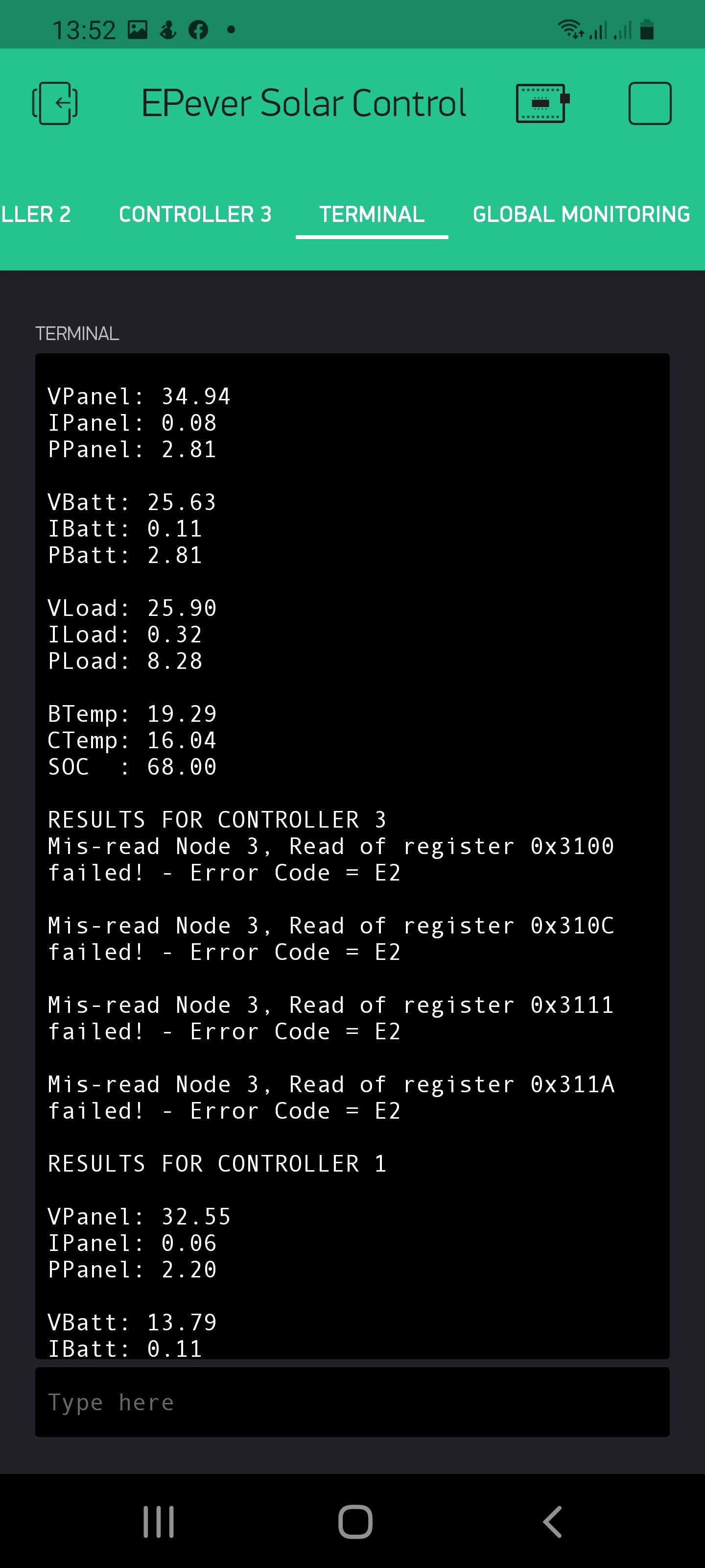
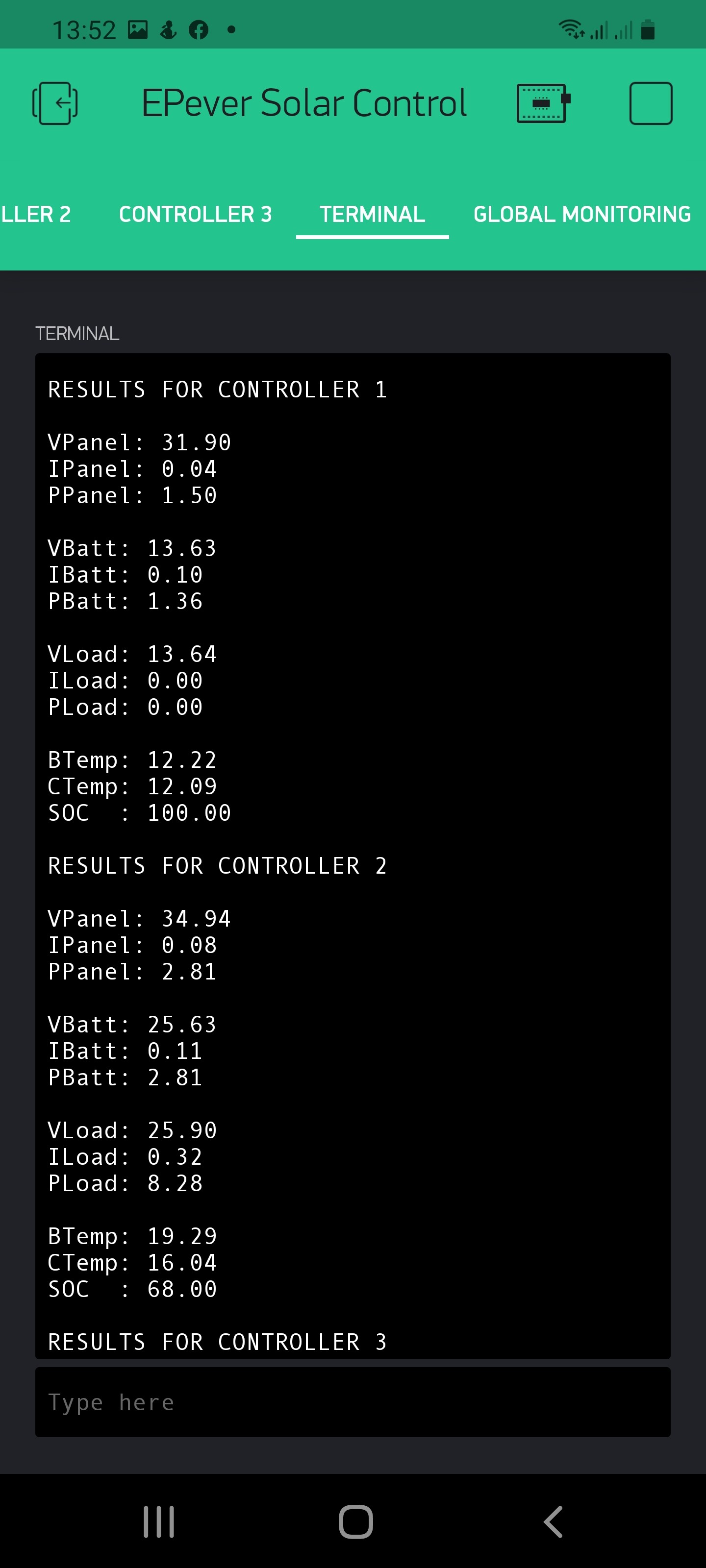
terminal.print("RESULTS FOR CONTROLLER ");
terminal.println(next_controller);
uint8_t result;
// Read 6 registers starting at 0x3100)
node.clearResponseBuffer();
result = node.readInputRegisters(0x3100, 8);
if (result == node.ku8MBSuccess)
{
float pV = node.getResponseBuffer(PANEL_VOLTS)/100.0f;
float pI = node.getResponseBuffer(PANEL_AMPS)/100.0f;
float pP = (node.getResponseBuffer(PANEL_POWER_L) |
(node.getResponseBuffer(PANEL_POWER_H) << 8))/100.0f;
float bV = node.getResponseBuffer(BATT_VOLTS)/100.0f;
float bI = node.getResponseBuffer(BATT_AMPS)/100.0f;
float bP = (node.getResponseBuffer(BATT_POWER_L) |
(node.getResponseBuffer(BATT_POWER_H) << 8))/100.0f;
terminal.println();
terminal.print("VPanel: ");
terminal.println(pV);
terminal.print("IPanel: ");
terminal.println(pI);
terminal.print("PPanel: ");
terminal.println(pP);
terminal.println();
terminal.print("VBatt: ");
terminal.println(bV);
terminal.print("IBatt: ");
terminal.println(bI);
terminal.print("PBatt: ");
terminal.println(bP);
terminal.println();
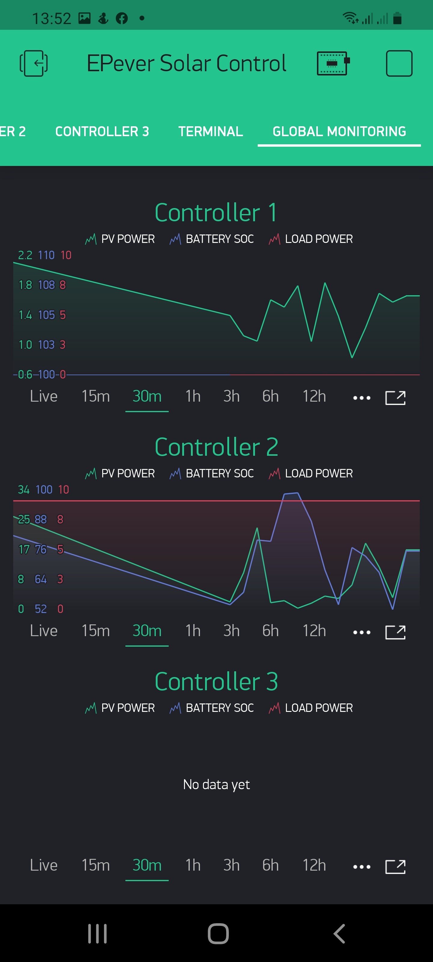
Blynk.virtualWrite((next_controller * 20), pV); // Virtual pins 20, 40, 60 etc
Blynk.virtualWrite((next_controller * 20)+1, pI); // Virtual pins 21, 41, 61 etc
Blynk.virtualWrite((next_controller * 20)+2, pP); // Virtual pins 22, 42, 62 etc
Blynk.virtualWrite((next_controller * 20)+3, bV); // Virtual pins 23, 43, 63 etc
Blynk.virtualWrite((next_controller * 20)+4, bI); // Virtual pins 24, 44, 64 etc
Blynk.virtualWrite((next_controller * 20)+5, bP); // Virtual pins 25, 45, 65 etc
}
else
{
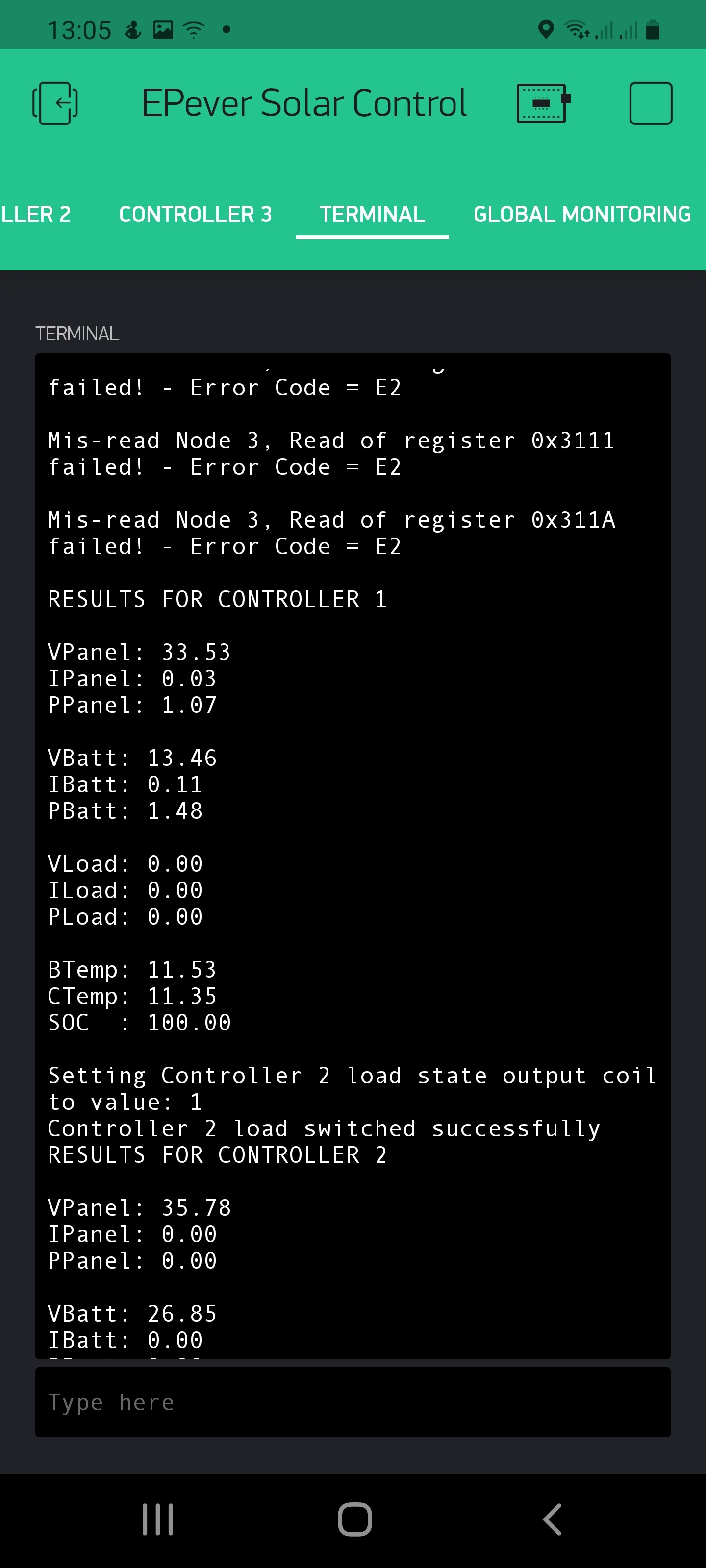
terminal.print("Mis-read Node ");
terminal.print(next_controller);
terminal.print(", Read of register 0x3100 failed! - Error Code = ");
terminal.println(result, HEX);
terminal.println();
}
// Read 6 registers starting at 0x310C)
node.clearResponseBuffer();
result = node.readInputRegisters(0x310c, 4);
if (result == node.ku8MBSuccess)
{
float lV = node.getResponseBuffer(LOAD_VOLTS)/100.0f;
float lI = node.getResponseBuffer(LOAD_AMPS)/100.0f;
float lP = (node.getResponseBuffer(LOAD_POWER_L) |
(node.getResponseBuffer(LOAD_POWER_H) << 8))/100.0f;
terminal.print("VLoad: ");
terminal.println(lV);
terminal.print("ILoad: ");
terminal.println(lI);
terminal.print("PLoad: ");
terminal.println(lP);
terminal.println();
Blynk.virtualWrite((next_controller * 20)+6, lV); // Virtual pins 26, 46, 66 etc
Blynk.virtualWrite((next_controller * 20)+7, lI); // Virtual pins 27, 47, 67 etc
Blynk.virtualWrite((next_controller * 20)+8, lP); // Virtual pins 28, 48, 68 etc
}
else
{
terminal.print("Mis-read Node ");
terminal.print(next_controller);
terminal.print(", Read of register 0x310C failed! - Error Code = ");
terminal.println(result, HEX);
terminal.println();
}
// Read 2 registers starting at 0x3110)
node.clearResponseBuffer();
result = node.readInputRegisters(0x3110, 2);
if (result == node.ku8MBSuccess)
{
float bT = node.getResponseBuffer(BATT_TEMP)/100.0f;
float cT = node.getResponseBuffer(CONTROL_TEMP)/100.0f;
terminal.print("BTemp: ");
terminal.println(bT);
terminal.print("CTemp: ");
terminal.println(cT);
Blynk.virtualWrite((next_controller * 20)+9, bT); // Virtual pins 29, 49, 69 etc
Blynk.virtualWrite((next_controller * 30)+0, cT); // Virtual pins 30, 50, 70 etc
}
else
{
terminal.print("Mis-read Node ");
terminal.print(next_controller);
terminal.print(", Read of register 0x3111 failed! - Error Code = ");
terminal.println(result, HEX);
terminal.println();
}
// Read 1 register starting at 0x311A)
node.clearResponseBuffer();
result = node.readInputRegisters(0x311A, 1);
if (result == node.ku8MBSuccess)
{
float bSOC = node.getResponseBuffer(BATT_SOC)/1.0f;
terminal.print("SOC : ");
terminal.println(bSOC);
terminal.println();
Blynk.virtualWrite((next_controller * 30)+1, bSOC); // Virtual pins 31, 51, 71 etc
}
else
{
terminal.print("Mis-read Node ");
terminal.print(next_controller);
terminal.print(", Read of register 0x311A failed! - Error Code = ");
terminal.println(result, HEX);
terminal.println();
}
}
// Callback to on/off button state changes from the Blynk app for Controller 1
BLYNK_WRITE(V103)
{
uint8_t newState = (uint8_t)param.asInt();
terminal.print("Setting Controller 1 load state output coil to value: ");
terminal.println(newState);
node.begin(1, Serial); // Select Controller 1
result = node.writeSingleCoil(0x0002, newState); // Turn the load on or off
if (result == node.ku8MBSuccess)
{
terminal.println("Controller 1 load switched successfully");
terminal.println();
}
else
{
terminal.println("Controller 1 load switching failed");
terminal.println();
}
}
// Callback to on/off button state changes from the Blynk app for Controller 2
BLYNK_WRITE(V113)
{
uint8_t newState = (uint8_t)param.asInt();
terminal.print("Setting Controller 2 load state output coil to value: ");
terminal.println(newState);
node.begin(2, Serial); // Select Controller 2
result = node.writeSingleCoil(0x0002, newState); // Turn the load on or off
if (result == node.ku8MBSuccess)
{
terminal.println("Controller 2 load switched successfully");
terminal.println();
}
else
{
terminal.println("Controller 2 load switching failed");
terminal.println();
}
}
// Callback to on/off button state changes from the Blynk app for Controller 3
BLYNK_WRITE(V123)
{
uint8_t newState = (uint8_t)param.asInt();
terminal.print("Setting Controller 3 load state output coil to value: ");
terminal.println(newState);
node.begin(3, Serial); // Select Controller 3
result = node.writeSingleCoil(0x0002, newState); // Turn the load on or off
if (result == node.ku8MBSuccess)
{
terminal.println("Controller 3 load switched successfully");
terminal.println();
}
else
{
terminal.println("Controller 3 load switching failed");
terminal.println();
}
}
void loop()
{
ArduinoOTA.handle();
timer.run();
Blynk.run();
if(WiFi.status() != WL_CONNECTED)
{
}
}
void preTransmission()
{
digitalWrite(MAX485_RE, 1);
digitalWrite(MAX485_DE, 1);
}
void postTransmission()
{
digitalWrite(MAX485_RE, 0);
digitalWrite(MAX485_DE, 0);
}