Just sharing my code. This is used to automate control of a chicken coop that is powered via a solar array\battery bank. It is used to read light and adjust as needed (chickens lay more eggs with 12 hours of light). It turns on a fan if it gets over the heat threshold (based on the heat index, not temperature). Code ouputs in degrees Fahrenheit (I am in the US, which still lags on adopting the Metric system) . Arduino writes slider values to EEProm, in case of power outage the values are read back at void setup(), to make sure the settings reflect the values before loss of power.
setup runs currently on an Arduino Mega 2560 with an adafruit Huzzah module for wifi. Also 2 relays, DHT11 temp and humidity sensor, GY-30 light sensor.
I will add a fritzing image someday when I get time, but the code tells you which pins are required.
Future plans to add door control, solar panel tracking mount and explore using the Huzzah module stand alone, without the Arduino. This is my first time using arduino, so I am learning as I go, and as my knowledge changes, my approach\coding\hardware changes too. 
This could be used for greenhouses, aquariums, basements, etc… anything you want to control light and temp…Share your uses if you implement something on this code base!
Code seems to work pretty well, I am using the android OS, but feel free to suggest changes, as I am a beginner at this and still learning.
Also worth noting, a lot of this code is taken from other projects and example sketches, and I failed to keep track of who should get credit for the bits of code. Some is original code, some isn’t.
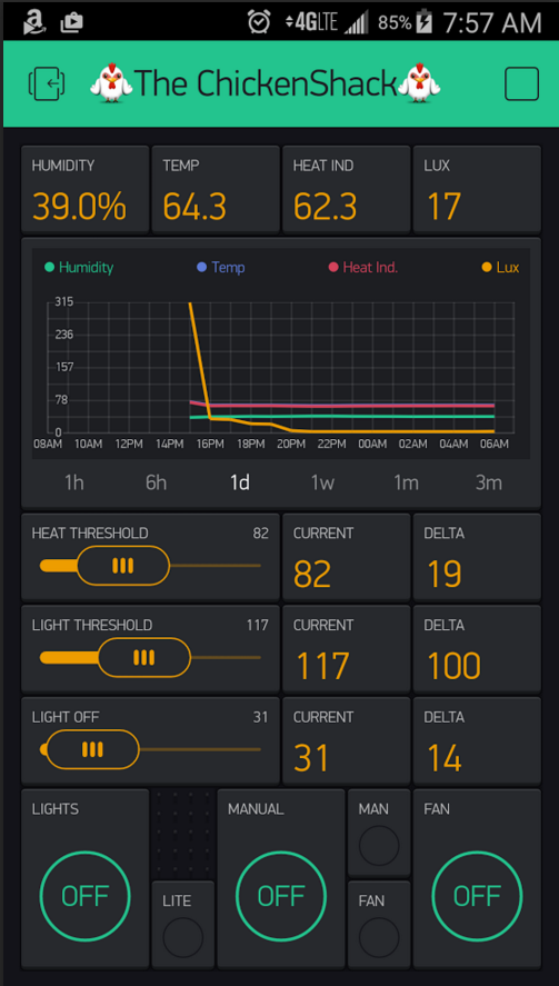
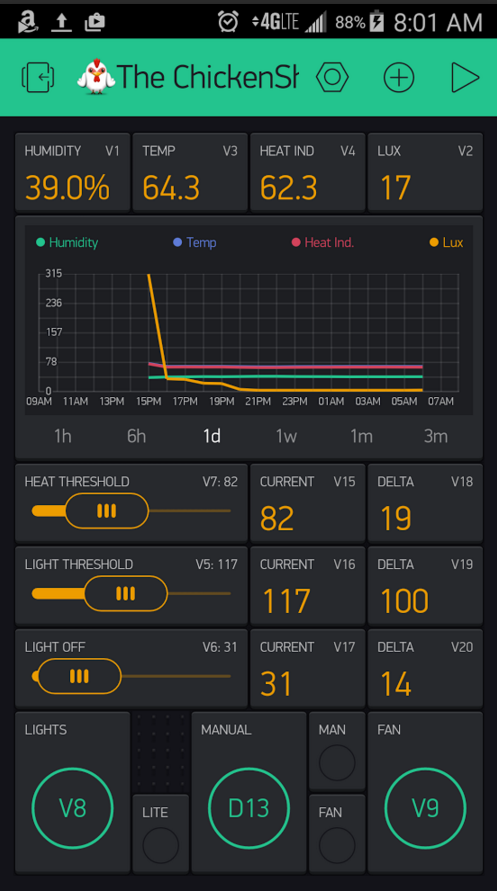
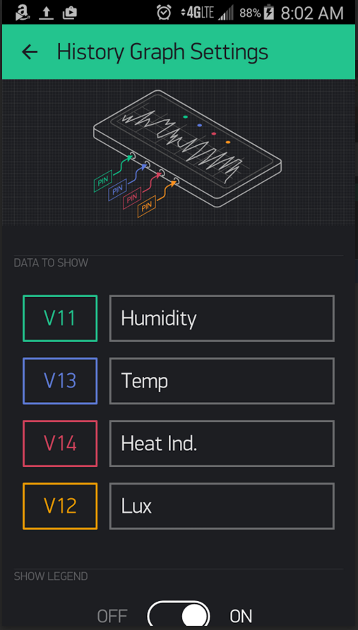
I’ve made  The ChickenShack:rooster: app. You are welcome to try it out!
To start using it:
- Download Blynk App: http://j.mp/blynk_Android or http://j.mp/blynk_iOS
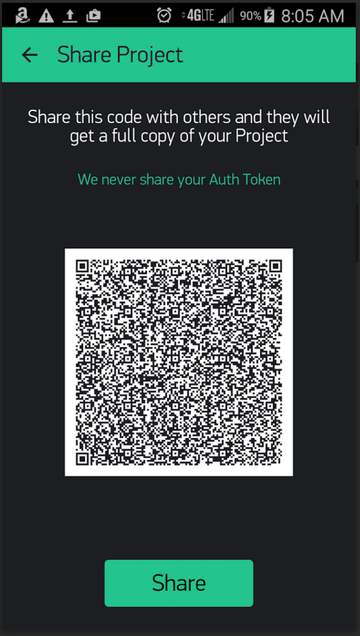
- Touch the QR icon and point the camera to the code below or open the link below - http://tinyurl.com/j58wh9j
- Enjoy my app!
        /* Used to automate a chicken coop.
         * Monitors Heat, Humidity, Heat Index and Light Saturation
         * when the temp gets too hot based on heat index, then turn on a relay connected to an exhaust fan
         * when the light drops below a threshold, turn on a relay connected to an LED array of lights (chickens like 12 hour days, they lay more eggs :)  )
         * when the light drops below a different and lower threshold, turn the LEDs off. This allow me to add some light at dusk, but turn off at night time
         * basically adding light at the end of the day during DST
         * Future expansion for watering needs and automatic\RFID coop door open and close
         */
        //#define BLYNK_DEBUG // Optional, this enables lots of prints
        //#define BLYNK_PRINT Serial //this causes buffer overflow as it competes with the console serial out

        #include <BlynkSimpleShieldEsp8266_HardSer.h>
        #include <DHT.h>
        #define DHTTYPE DHT11
        #define DHTPIN 11
        #include <SimpleTimer.h>
        #include <EEPROM.h>
        //#include <ESP8266_HardSer.h>
        #include <SPI.h>
        #include <Wire.h>
        float hum;
        float t;
        float f;
        float hif;
        int photocellPin = 1;
        int FanRelayPin = 9;
        int LightRelayPin = 8;
        int photocellReading;
        int luxdifference;
        /** the current address in the EEPROM (i.e. which byte we're going to write to next) **/
        int addressTempHum = 0;
        int addressLightThresh = 1;
        int addressLightOff = 2;
        long LightThresholdValue; //byte allows to be written to eeprom, but max is 255
        long LightOffValue;
        long HeatThresholdValue;
        int HeatDifference;
        int LightOffDifference;
        int ManualMode;
        int ManualLights;
        int ManualFan;
        int LiteLEDStatus;
        int FanLEDStatus;
        int ManualModeStatus; //init with manual mode off in case of power loss, it comes up with last settings
        int lastButtonStateLiteLed;
        int lastButtonStateFanLed;
        int lastButtonStateManualMode;

        const char* ssid = "YOURSSID";
        const char* password = "YOURPASSWORD";
        WidgetLED led1(30); //LightLED in blynk app
        WidgetLED led2(31);//FanLED in blynk app
        WidgetLED led3(10);//wifi connection light
        WidgetLED led4(28);//manual led for light side
        //WidgetLCD lcd(9);
        unsigned long previousMillis; //for blynk slider debounce
        unsigned long waitTime = 3000; //for blynk slider debounce

        DHT dht(DHTPIN, DHTTYPE);
        //float humidity, temp_f;  // Values read from sensor
        int BH1750_address = 0x23; // i2c Addresse//for GY-30 light sensor
        byte buff[2];// i2c Addresse//for GY-30 light sensor

        // You should get Auth Token in the Blynk App.
        // Go to the Project Settings (nut icon).
        char auth[] = "YOURBLYNKAUTHCODE";
        // Set ESP8266 Serial object
        #define EspSerial Serial
        ESP8266 wifi(EspSerial);
        SimpleTimer timer;

        void setup()
        {
        timer.setInterval(2000, LiteLed);
        timer.setInterval(2000, FanLed);
        timer.setInterval (2000, SendTempHumidity);
        timer.setInterval (2000, SendDataLight); //get light sensor data
        timer.setInterval (2000, LightDelta); //get delta between current and threshold settings
        timer.setInterval (2000, HeatDelta); //get delta between heat index and threshold settings
        timer.setInterval (2000, LightOffDelta);
        timer.setInterval (2000, ManualModeLed);
        //timer.setInterval (30000, ResetArduino);
        //timer.setInterval (2000, DebugData);
        //timer.setInterval (2000, ManualModeLed2);
        ManualModeStatus = 0; //init with manual mode off in case of power loss, it comes up with last settings
        lastButtonStateLiteLed = 0;
        lastButtonStateFanLed = 0;
        lastButtonStateManualMode = 0;

        // Set ESP8266 baud rate
        EspSerial.begin(115200);
        //EspSerial.begin(38400);
        Serial.begin(115200);
        //Serial.begin(38400);
        Wire.begin();//for GY-30 light sensor
        //EEPROM.read(0); //read data stored in EEProm for parameters
        Serial.print("LightThresholdValueFromEEPROM: ");
        //Readind and sending first long.
        LightThresholdValue = EEPROMReadlong(0);
        Serial.println(LightThresholdValue);

        //EEPROM.read(1); //written as byte, but 255 is the max value
        Serial.print("LightOffValueFromEEPROM: ");
        LightOffValue = EEPROMReadlong(4);
        //Readind and sending first long.
        Serial.println(LightOffValue);

        //EEPROM.read(2); //written as byte, but 255 is the max value
        Serial.print("HeatThresholdValueFromEEPROM: ");
        HeatThresholdValue = EEPROMReadlong(8);
        //Reading and sending first long.
        Serial.println(HeatThresholdValue);
        dht.begin();// initialize temperature sensor

        Blynk.begin(auth, wifi, ssid, password);//This works, just testing other wifi libraries
        //wait for blynk connection
        while (Blynk.connect() == false) {
        // Wait until connected
        }
        pinMode(8, OUTPUT);      // sets the digital pin as output
        digitalWrite(8,HIGH); //turn off light pin on init
        pinMode(9, OUTPUT);      // sets the digital pin as output
        digitalWrite(9, HIGH); //turn off fan pin on init
        pinMode(13, OUTPUT);      // sets the digital pin as output
        digitalWrite(13, LOW); //turn off manual mode pin on init this is backwards compared to the relay
        led1.off();
        led2.off();
        led3.off();
        led4.off();
        }//end setup()

        //int eeprom_address = 0; //We will start writing at the first memory address
        long address=0;//Starting at the first byte on the eeprom.

        void SendTempHumidity() {
         //delay(1000); //see if this help with wifi drops
        hum = dht.readHumidity(); //Read humidity
        t = dht.readTemperature(); //Read temperature
        f = dht.readTemperature(true); //Read temperature as Fahrenheit
        hif = dht.computeHeatIndex(f, hum);
        int value1=hum*10;
        String str1;
        char result1[5];
        result1[0]=(value1/100)+'0';
        result1[1]=((value1/10)%10)+'0';
        result1[2]='.';
        result1[3]=(value1%10)+'0';
        result1[4]='\0';
        str1 +=result1;
        str1 +="%";
        //char buf[str.length()+1];
        char buf1[8];
        str1.toCharArray(buf1,sizeof(buf1));

        Blynk.virtualWrite(1, buf1); //write humidity with percent sign to virtual pin 1
        Blynk.virtualWrite(11, hum); //write humidity witouth percent sign to virtual pin 11
        int value2=f*10;
        String str2;
        char result2[5];
        result2[0]=(value2/100)+'0';
        result2[1]=((value2/10)%10)+'0';
        result2[2]='.';
        result2[3]=(value2%10)+'0';
        result2[4]='\0';
        str2 +=result2;
        //str2 +="°";
        //char buf[str.length()+1];
        char buf2[8];
        str2.toCharArray(buf2,sizeof(buf2));
        Blynk.virtualWrite(3, buf2); //write temp with percent sign to virtual pin 3
        Blynk.virtualWrite(13, f); //write temp without percent sign to virtual pin 13
        int value3=hif*10;
        String str3;
        char result3[5];
        result3[0]=(value3/100)+'0';
        result3[1]=((value3/10)%10)+'0';
        result3[2]='.';
        result3[3]=(value3%10)+'0';
        result3[4]='\0';
        str3 +=result3;
        //str3 +="°";
        //char buf[str.length()+1];
        char buf3[8];
        str3.toCharArray(buf3,sizeof(buf3));

        Blynk.virtualWrite(4, buf3); //write fahrenheit heat index with percent sign to virtual pin 4
        Blynk.virtualWrite(14, hif); //write fahrenheit heat index without percent sign to virutal pin 14

        if (hif >=HeatThresholdValue && ManualModeStatus != 1){
        digitalWrite(FanRelayPin, LOW); //latch the fan relay to activate the fan
        }else if (ManualModeStatus != 1) {
        digitalWrite (FanRelayPin, HIGH); //turn off relay
        }
        }
        void SendDataLight(){
        photocellReading = analogRead(photocellPin);
        Blynk.virtualWrite(2, photocellReading);
        Blynk.virtualWrite(12, photocellReading);

        if (photocellReading <= LightThresholdValue && photocellReading >= LightOffValue  && ManualModeStatus != 1){
        digitalWrite(LightRelayPin, LOW); //latch the light relay to activate the supplemental light
        }else if (ManualModeStatus != 1){
        digitalWrite(LightRelayPin,HIGH); //unlatch relay to turn off lights
        }
        }
        BLYNK_WRITE(V5) { //working 2/23/16
        LightThresholdValue = param.asInt(); //    / 4.02
        address=0;
        EEPROMWritelong(address, LightThresholdValue);//Writing first long.
        Blynk.virtualWrite (16, EEPROMReadlong(0)); //write temp without percent sign to virtual pin 13
        }


        BLYNK_WRITE(V6) {
        LightOffValue = param.asInt();// + 10;
        address=4;
        EEPROMWritelong(address, LightOffValue);//Writing first long.
        Blynk.virtualWrite (17, EEPROMReadlong(4)); //write temp without percent sign to virtual pin 17
        }

        BLYNK_WRITE(V7) {
        HeatThresholdValue = param.asInt();// + 10;
        address=8;
        EEPROMWritelong(address, HeatThresholdValue);//Writing first long.
        Blynk.virtualWrite(15, EEPROMReadlong(8)); //write temp without percent sign to virtual pin 15
        }

        void loop()
        {
        Blynk.run();
        timer.run();

        }//end loop

        void ManualModeLed(){
        ManualModeStatus = digitalRead(13);
        //Serial.println(" ");
        //Serial.print("ManualMode: ");
        //Serial.println(ManualModeStatus);
        if (ManualModeStatus != lastButtonStateManualMode) {
        if (ManualModeStatus == 1){
        led3.on();
        //led4.on();
        } else
        led3.off();
        //led4.off();
        }
        lastButtonStateManualMode = ManualModeStatus;
        }
        /*void ManualModeLed2(){
        ManualModeStatus = digitalRead(13);
        Serial.println(" ");
        Serial.print("ManualMode: ");
        Serial.println(ManualModeStatus);
        if (ManualModeStatus != lastButtonStateManualMode) {
        if (ManualModeStatus == 1){
        led4.on();
        } else
        led4.off();
        }
        lastButtonStateManualMode = ManualModeStatus;
        }
        */
        //this is to work around the sainsmart relay, it is backwards compared to most...
        BLYNK_WRITE(8) //light
        {
          if (param.asInt()) {
            digitalWrite(8, LOW);
          } else {
            digitalWrite(8, HIGH);
          }
        }
        //this is to work around the sainsmart relay, it is backwards compared to most...
        BLYNK_WRITE(9) //fan
        {
          if (param.asInt()) {
            digitalWrite(9, LOW);
          } else {
            digitalWrite(9, HIGH);
          }
        }


        void FanLed(){
        FanLEDStatus = digitalRead(9);
        if (FanLEDStatus != lastButtonStateFanLed) {
        if (FanLEDStatus == 1){
        led2.off();
        }  else
        led2.on();
        }
        lastButtonStateFanLed = FanLEDStatus;
        }
        void LiteLed(){
        LiteLEDStatus = digitalRead(8);
        if (LiteLEDStatus != lastButtonStateLiteLed) {
        if (LiteLEDStatus == 1){
        led1.off();
        }  else
        led1.on();
        }
        lastButtonStateLiteLed = LiteLEDStatus;
        }

        //This function will write a 4 byte (32bit) long to the eeprom at
        //the specified address to address + 3....no decimals
        void EEPROMWritelong(int address, long value)
              {
              //Decomposition from a long to 4 bytes by using bitshift.
              //One = Most significant -> Four = Least significant byte
              byte four = (value & 0xFF);
              byte three = ((value >> 8) & 0xFF);
              byte two = ((value >> 16) & 0xFF);
              byte one = ((value >> 24) & 0xFF);

              //Write the 4 bytes into the eeprom memory.
              EEPROM.write(address, four);
              EEPROM.write(address + 1, three);
              EEPROM.write(address + 2, two);
              EEPROM.write(address + 3, one);
              }

        //This function will return a 4 byte (32bit) long from the eeprom
        //at the specified address to address + 3.
        long EEPROMReadlong(long address)
              {
              //Read the 4 bytes from the eeprom memory.
              long four = EEPROM.read(address);
              long three = EEPROM.read(address + 1);
              long two = EEPROM.read(address + 2);
              long one = EEPROM.read(address + 3);

              //Return the recomposed long by using bitshift.
              return ((four << 0) & 0xFF) + ((three << 8) & 0xFFFF) + ((two << 16) & 0xFFFFFF) + ((one << 24) & 0xFFFFFFFF);
              }
        void LightDelta(){
        if (LightThresholdValue <= photocellReading){
        luxdifference = photocellReading - LightThresholdValue;
        }else {
        luxdifference = LightThresholdValue - photocellReading;
        }
        Blynk.virtualWrite (19, luxdifference);
        }

        void HeatDelta(){
        if (hif>=HeatThresholdValue){
          HeatDifference = hif - HeatThresholdValue;
        }else{
          HeatDifference = HeatThresholdValue - hif;
        }
        Blynk.virtualWrite (18, HeatDifference);
        }

        void LightOffDelta(){
        if (photocellReading>=LightOffValue){
        LightOffDifference = photocellReading - LightOffValue;
        }else{
        LightOffDifference = LightOffValue - photocellReading;
        }
        Blynk.virtualWrite (20, LightOffDifference);
        }
        //void ResetArduino(){
        //delay(3000); //this delay is longer than the timers, so if nothing happens in this time something is wrong
        //if (Blynk.connect() == false) {
        //Serial.println();
        //Serial.print("No connection to Blynk, resetting Arduino");
        //delay(1000);
        //pinMode(12, OUTPUT);
        //digitalWrite(12,LOW); //pin 12 is connected to reset pin via a 1K resistor
        //}
        //}

        BLYNK_CONNECTED() //synch button states when connected
        {
        //Blynk.syncAll(); //this crashes the connection
        }

 .
.