Understood. I will follow your recommendation. I have this PSU

I think it will be enough to supply NodeMCU, Relay Board and electro valves.
Thks again.
My next idea is to add a rain delay.
Understood. I will follow your recommendation. I have this PSU
I think it will be enough to supply NodeMCU, Relay Board and electro valves.
Thks again.
My next idea is to add a rain delay.
You are joking - right?
9v will kill your NodeMCU.
Pete.
True. Sorry. This is only for the electro valves. I will use this one.

Dear Pete,
I did like you told me
5V Positive (+) from PSU connects to:
5V Negative(-) from PSU connects to:
When I connect PSU to electricity the NodeMCU run ok and I can control it from the mobile, the problem is the relay. It starts ON and when I click in the mobile app button to switch on/off it do a strange noise and the light do something strange.
Doing it like manufactur company told me I can switch on/off relay light but it doesn’t do any noise then I assume the coil is not working.
Any idea?
Sounds like either a poor ground connection, or a power supply that’s not able to deliver enough current (or one that’s delivering the wrong voltage).
Pete.
I found this PSU which can deliver 3,3v and 5v. Input can be the 9v PSU that I will use for the electro valves. With 1 cable I can supply energy to the 3 boards.

Then I can connect indivially the nodemcu to th YWRobots psu and the 5v output to the relay board. I will keep connection between nodemcu and relay board via Pin and IN pins.
What do you thing?
You don’t need 3.3 and 5v supplies. The NodeMCU is fine with 5v applied to the VCC/5v pin.
I wouldn’t use one of these breadboard power supplies for powering a project like this.
Just grab a 230v to 5v power supply capable of delivering a couple of amps and it’ll be fine.
Pete.
This is relay schema. Th Vcc/jdvcc are pins

Maybe it can help you to tell me how to connect each cable.
The jumper needs to be in place across JD-VCC and VCC then connect as I’ve described several times before…
Pete.
Pete. I did, psu positive to nodemcu 5V and Relay board VCC + psu negative to GND in mcu and relay and it doesn’t work. 
Maybe
5V Positive (+) from PSU connects to:
5V Negative(-) from PSU connects to:
Then from nodemcu 3,3v to VCC close to JDVCC.
It is an idea.
I had a look in my parts box and found a relay that looks very similar to the one you’re using.
I put the jumper in place between JD-VCC and VCC then connected it to a 5v power supply using the red and black wires in the photo below.
The green wire in the photo is connected to Ground on the power supply, and although you can’t see it very well in the photo, the LED labelled IN2 is lit, and relay 2 is activated.
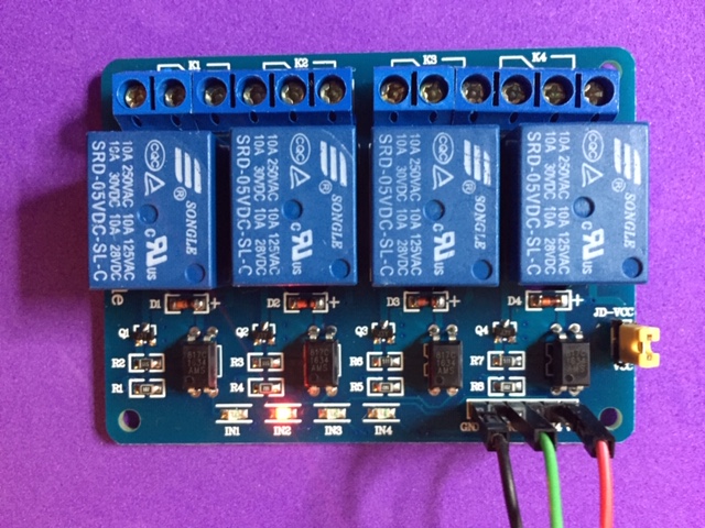
If your relay doesn’t do this then either your power supply or relay board is faulty, or it’s not an active LOW relay board.
If it’s an active HIGH relay board then applying 5v+ to any of pins IN1 to IN4 should activate the corresponding relay. If it doesn’t, then we’re down to either a faulty power supply or a faulty relay board.
Pete.
Dear Pete,
My board is doing the same than your one.
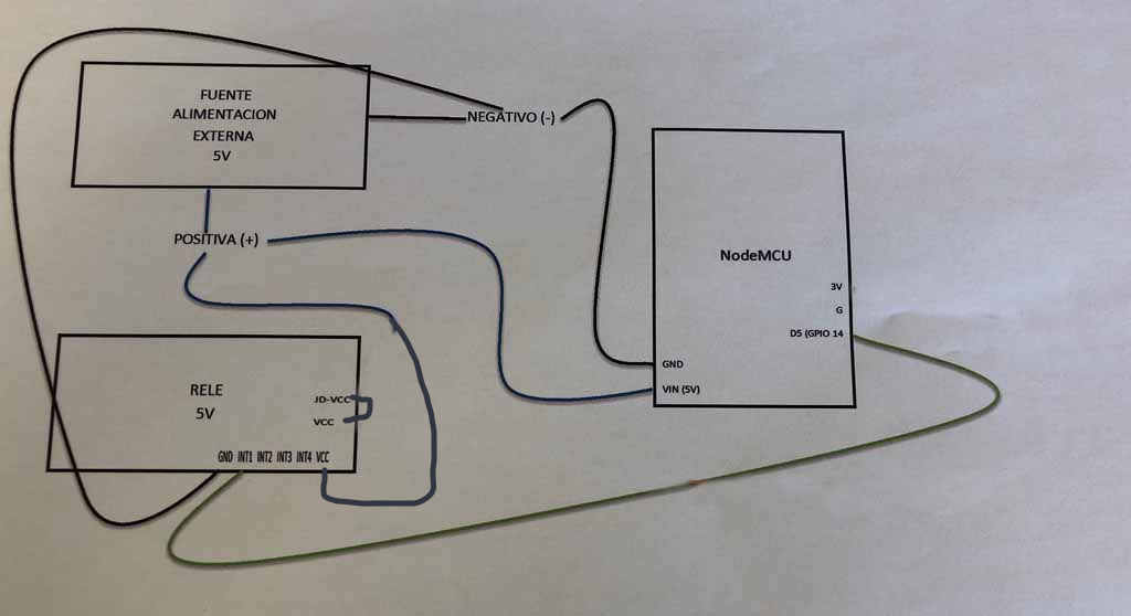
Arrived to this point. Why I cannot supply electricity to the NodeMCU board then to connect 3.3V or 5V to VCC in the relay board and GND from NodeMCU to relay board? Also connecting Pins to INT. With this schema I runned perfectly. I was able to connect and disconnect relays.
Thks a lot for your support.
This is how I think It will work

Okay, this is the last time that I’m going to reply about the way in which I think you should wire this. I keep repeating myself and it’s getting a bit tiresome.
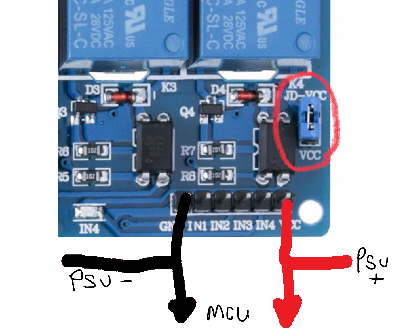
If I was going to do this, I’d wire it like this:
The jumper between the JD-VCC and VCC pins needs to be in place.
The 5v positive needs to go to Vcc on the relay board and Vin(5v) on the NodeMCU
The negative needs to go to GND on both the relay board and the NodeMCU
When your NodeMCU wants to activate Relay 1 on the relay board, it will pull pin D5 (GPIO14) LOW - in other words, it will connect pin IN1 on the relay board to ground, via GPIO14.
You’ve already said yesterday that if you simulate what I did with my relay board then yours does the same thing. Therefore when you wire it like this and pull pin IN1 on the relay board LOW using GPIO14, the relay will operate.
If this isn’t happening then you either have a problem with your wiring, or you haven’t set-up your code to work correctly with an active LOW relay board.
Pete.