Doubts current sensor ACS712 30A + Nodemcu ESP8266

No, but I live on a “Greek” island.

anyway thnx i wil study more and see what happens

I have the same Costas´s ideia, if you remove this part of the code should be work, but you need to send less than 10 values per second to Blynk Cloud, otherwise you hardware will be disconeted. Use more than 1s to read/send the measure.

I tried to read my ACS712 without Blynk for a while, but I couldn´t read the correct value using an arduino. I used tree or four diferents codes, but nothing… As soon as possible I will try using your code @Polikarpos. thanks

I´m trying to measure a current of a “iron clothes” (I don´t know the correct name of this equipment =D), I should read something like 10A, but the ACS712 30A only read:

0.08 Amps RMS
0.05 Amps RMS
0.08 Amps RMS
0.05 Amps RMS
0.08 Amps RMS
0.08 Amps RMS
0.08 Amps RMS
0.05 Amps RMS
0.05 Amps RMS
0.08 Amps RMS

Should I do something else? like a calibration, or something like that? I´m using the same @Polikarpos code.

Thanks guys

I found the problem. was my severals nodeMCU connected on my computer at the same time!!! OMG! so many ports, and I was uploading the code to the wrong nodemcu…

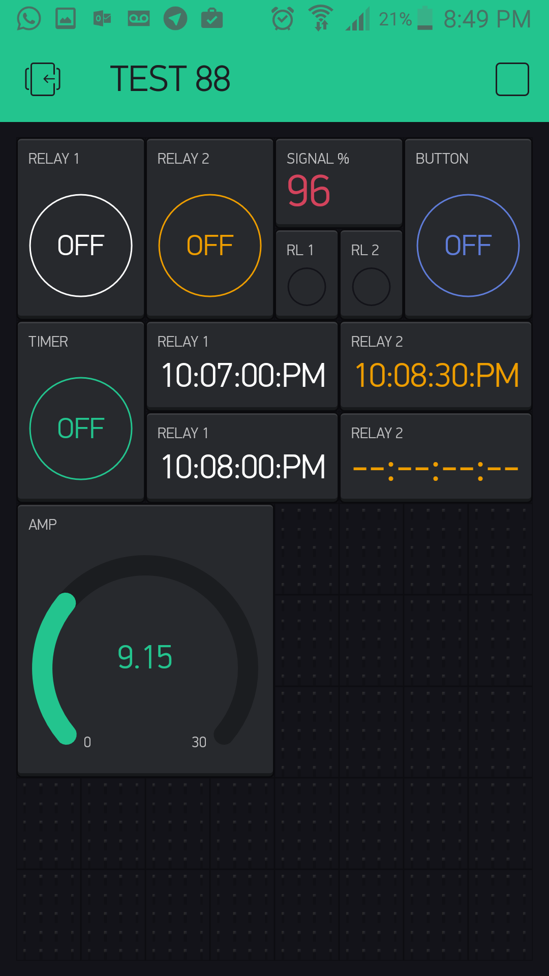
I did the code. the loop ask the read function using SimpleTimer, 1 time per second and send the value to the blynk on V13 I used a GAUGE widget.

#define BLYNK_PRINT Serial    // Comment this out to disable prints and save space
#include <ESP8266WiFi.h>
#include <BlynkSimpleEsp8266.h>
#include <SimpleTimer.h>

char auth[] = "...";
char ssid[] = "....";
char password[] = "...";


const int sensorIn = A0;
int mVperAmp = 66; // use 100 for 20A Module and 66 for 30A Module

double Voltage = 0;
double VRMS = 0;
double AmpsRMS = 0;

SimpleTimer timer0;

void readACS712() {
 Voltage = getVPP();
 VRMS = (Voltage/2.0) *0.707; 
 AmpsRMS = (VRMS * 1000)/mVperAmp;
 Serial.print(AmpsRMS);
 Serial.println(" Amps RMS");
 Blynk.virtualWrite(V13, AmpsRMS);
 pinMode(sensorIn, INPUT);
}

void setup(){ 
 Serial.begin(9600);
 Blynk.begin(auth, ssid, password);
 timer0.setInterval(1000L, readACS712);
 
}

void loop(){
 Blynk.run();
 timer0.run();
 
}

float getVPP()
{
  float result;
  
  int readValue;             //value read from the sensor
  int maxValue = 0;          // store max value here
  int minValue = 1024;          // store min value here
  
   uint32_t start_time = millis();
   while((millis()-start_time) < 1000) //sample for 1 Sec
   {
       readValue = analogRead(sensorIn);
       // see if you have a new maxValue
       if (readValue > maxValue) 
       {
           /*record the maximum sensor value*/
           maxValue = readValue;
       }
       if (readValue < minValue) 
       {
           /*record the maximum sensor value*/
           minValue = readValue;
       }
   }
   
   // Subtract min from max
   result = ((maxValue - minValue) * 5.0)/1024.0;
      
   return result;
 }
4 Likes

your code seems more legit than mine…i got it working by modifying float getVPP function and messing around with the times…it seems ok but i ll try your code too
here it is:

    #define BLYNK_PRINT Serial    // Comment this out to disable prints and save space
    #include <ESP8266WiFi.h>
    #include <BlynkSimpleEsp8266.h>
    #include <SimpleTimer.h>

    char auth[] = ".........";

    const int sensorIn = A0;
    int mVperAmp = 66; // use 100 for 20A Module and 66 for 30A Module


    double result;
    double VRMS = 0;
    double AmpsRMS = 0;

    SimpleTimer timer;
    void getVPP()
    {
       int readValue;             //value read from the sensor
      int maxValue = 0;          // store max value here
      int minValue = 1024;          // store min value here
      
       uint32_t start_time = millis();
       while((millis()-start_time) < 200) //sample for 1 Sec
       {
           readValue = analogRead(sensorIn);
           // see if you have a new maxValue
           if (readValue > maxValue) 
           {
               /*record the maximum sensor value*/
               maxValue = readValue;
           }
           if (readValue < minValue) 
           {
               /*record the maximum sensor value*/
               minValue = readValue;
           }
       }
       
       // Subtract min from max
       result = ((maxValue - minValue) * 5.0)/1024.0;
          
      VRMS = (result/2.0) *0.707; 
     AmpsRMS = (VRMS * 1000)/mVperAmp;
     Serial.print(AmpsRMS);
     Serial.println(" Amps RMS");
     Blynk.virtualWrite(7,AmpsRMS);
     if (AmpsRMS < 0.2)
    {
      Blynk.virtualWrite(8,"LAMP OFF");
    }
    else
    {
      Blynk.virtualWrite(8,"LAMP ON");
    }
      
     }


    void setup(){ 
     Serial.begin(9600);
     Blynk.begin(auth, ".......", "........");
         timer.setInterval(3000, getVPP);

void loop(){
  Blynk.run();
  
  timer.run();
}
      }

if i set timer.setInterval(1000, getVPP); instead of 3000 the nodemcu gets disconnected…

@Polikarpos I notice you have the sampling time down at 200ms. With @glauberbiro’s sketch it has a sampling time of 1s and a 1s loop. This means it is sampling constantly 24 hours a day which gives no time to do anything else. Normally this is a recipe for disaster.

Not sure why you need a 3s loop as 1s should be ok at first glance of your sketch.

so youre saying that sampling time down to 200ms is better?
i got both sketches working perfectly with no blynk disconnections but using at least 1.1s loop time. and sampling time less than 1s…0.5s works fine…cant explain why but suits me fine
3s or 2s loop is no problem…just want to control a device and get feedback of its status with blynk…

I always ask myself the question, how much time do I need and how accurate do I need to be? For example, I have a light on a timer which checks the light level every 30s (I think) to see if it needs to turn on. This is more than enough. I couldn’t care less if my lights go on 30s later or earlier, so I don’t need time critical code.

When operation a robot for example, it could well be more time critical. Always ask your self if there is room for performance improvement within these kind of applications. Measuring current is really not time critical. I try to make the biggest timer I can find which is still usable and use all Push frequency’s so I can update the App from the hardware side. Why? Because the hardware is, for now, the slowest component in the whole bunch of IoT devices. So I don’t want to push it (pun intended) to the limit. :slight_smile:

1 Like

I have no knowledge of what gives good sampling rates as far as monitoring DC current is concerned but sampling 100% of the time re @glauberbiro’s sketch is very bad for ioT devices.

So it is either increase the timer loop duration or decrease the sampling duration.

Only tests will give you the answer and Blynk can help with this too.
Put a couple of sliders in your project, one to change sampling duration and one to change timer loop duration to see which gives best results as far as stability and accuracy of data are concerned.

Edit: should have stated @glauberbiro’s sketch not @Polikarpos’ sketch.

1 Like

@Lichtsignaal is spot on. Some Blynkers seem to over sample at every opportunity and this is just a bad use of resources.

Just because an ESP CAN sample every few ms it doesn’t mean we should be doing so.
Temperature monitoring is a prime example where you see readings being taken every second when every 600 seconds is probably adequate.

2 Likes

got the point…thanx for your answers

Thanks Costas! I got it! it´s a nice ideia.

1 Like

@Polikarpos are you getting a signal current measure to detect if a lamp is on. I´m doing the same here, but I´m using a voltage detector to get if there is 127V at lamp. I´m using a 4N25 optocoupler working with a built in saturated transistor. Works like a charm and this kind of sensor can use a digital port instead of a analog port.

i ll try that optocoupler someday…my main goal is to get the current reading and calculate the consumption of power in kw…of a single device or a whole house…i just added this piece of code to practice my blynk skills

1 Like

Mmm… +1 for a whole house at the main circuit… Only one sensor needed! :wink:

1 Like

its better to use a ct sensor module 30 or 100A…no high voltage connections at all…

i mean ct sensor along winth nodemcu and blynk…

@Polikarpos probably you will have problems to use a high range CT sensor module to measure low values of current, to calculate power consumption.

I´m working in a project like yours. I´m thinking to use a CT sensor module (100A non invasive) one to each big current circuit, like kitchen, bathrooms. Low current circuits like lamps, I´m planning to use a simple invasive 20A/30A ACS712 module.

Do you know this project? https://openenergymonitor.org/ there are lots of information about it.