Okay, thanks for clarifying that. When I complete adding the rest of the code or I’ll post it for inspection or for others to use or improve.
Jeff
Following the suggestions of Pavel and John, I’ve substituted a segmented switch for the buttons. Much neater! Thanks for the suggestion. My only question is is there a way to increase the font size? On the other buttons, there is a choice of three font sizes. Can’t find it here.
//segmented switch is V1
//gauge is V0

//#define BLYNK_PRINT Serial
//#include <SPI.h>
#include <ESP8266WiFi.h>
#include <BlynkSimpleEsp8266.h>

// Your WiFi credentials.
#define BLYNK_PRINT Serial
#include <SPI.h>
char auth[] = "xxxxxxxxxxxxxxxxxxxxxxxxxxxxxxx"; //Enter the Auth code which was send by Blink

char ssid[] = "xxxxxxxxxxxxx";  //Enter your WIFI Name
char pass[] = "xxxxxxxxxxxx";  //Enter your WIFI Password

int tank1 =23;// arbitrary number as place holder for data sent from transmitter - just for testing now
int tank2 =55;// arbitrary number as place holder for data sent from transmitter - just for testing now
int tank3 = 75;// arbitrary number as place holder for data sent from transmitter - just for testing now
int tank4 = 17;// arbitrary number as place holder for data sent from transmitter - just for testing now

void setup() {
Blynk.begin(auth, ssid, pass);
}

void loop() {
  Blynk.run();
}

BLYNK_WRITE(V1) { // Segmented Switch
switch (param.asInt()){

    case 1: {
      Blynk.virtualWrite(V0, tank1);  // To Display Widget
        break;
      }
    case 2: {
      Blynk.virtualWrite(V0, tank2);  // To Display Widget
        break;
      }
  case 3: {
    Blynk.virtualWrite(V0, tank3);  // To Display Widget
        break;
      }
    case 4: {
      Blynk.virtualWrite(V0, tank4);  // To Display Widget
        break;
      }
        }
}
I still don’t think that this is really the best way to do this.
This will only display the data for that tank once, when the position of the segmented switch is changed.
My approach to this project would be to have the selected device taking water level readings on a regular basis - which could be every few seconds, minutes or hours, whichever is most appropriate - and writing the results out to your gauge widget. That way, whenever you open the app and look at the display, the data on the gauge will be the latest reading, not the one that was taken when the button was last changed state.
Pete.
1 Like
The data coming from the sensor (via the transmitter) will be updating every few seconds. Won’t the changes be reflected by the gauge, or only if it’s refreshed by pressing the appropriate tank button?
I’ll incorporate the above into the main program that has the sensor, and try it out. Once I get it running I’ll post it to see if you have suggestions how to improve it.
I should mention that while I’m monitoring four tanks, I have only ONE sensor in a special tank I constructed (the thin white one). This sensor tank is ALWAYS connected to the system and can be hooked in series to one of the four main tanks. I did this because it was unwieldy to have FOUR seperate sensors on the tanks that were not close together. However because the tanks are at slightly different elevations I’ve had to build in a factor to adjust for this. So (for instance) Tank1 = targetDistance, Tank 2 = (targetDistance +4), tank3 = targetDistance +7) and tank4 =(targetDistance =12). This works, so I just need a way of switching between tanks which I’ve done with above program. But you may be write that it won’t constantly update. I’ll find out tomorrow.
tanks… er I mean thanks.
Jeff
The extra information about there only actually being one sensor, which is physically moved from tank to tank, and which requires a calibration factor to be used for each tank, really ought to have been part of your initial post.
Prior to this, it appeared that there were four sensors, and you only wanted to display data from one of them.
Based on this additional information, it appears that what you actually want to to is:
-
Provide a visual representation in the app of which tank is currently being monitored
-
Apply the correct calibration value to the data prior to it being displayed.
If that is the case then your switch ought to be used to set a pointer variable, which is used to tell the rest of your code which calibration factor value(s) to use for the current tank. If the tanks aren’t identical in capacity, and you wish to show the current volume of water in gallons/litres then these calibration values would need to include this data for each tank.
Pete.
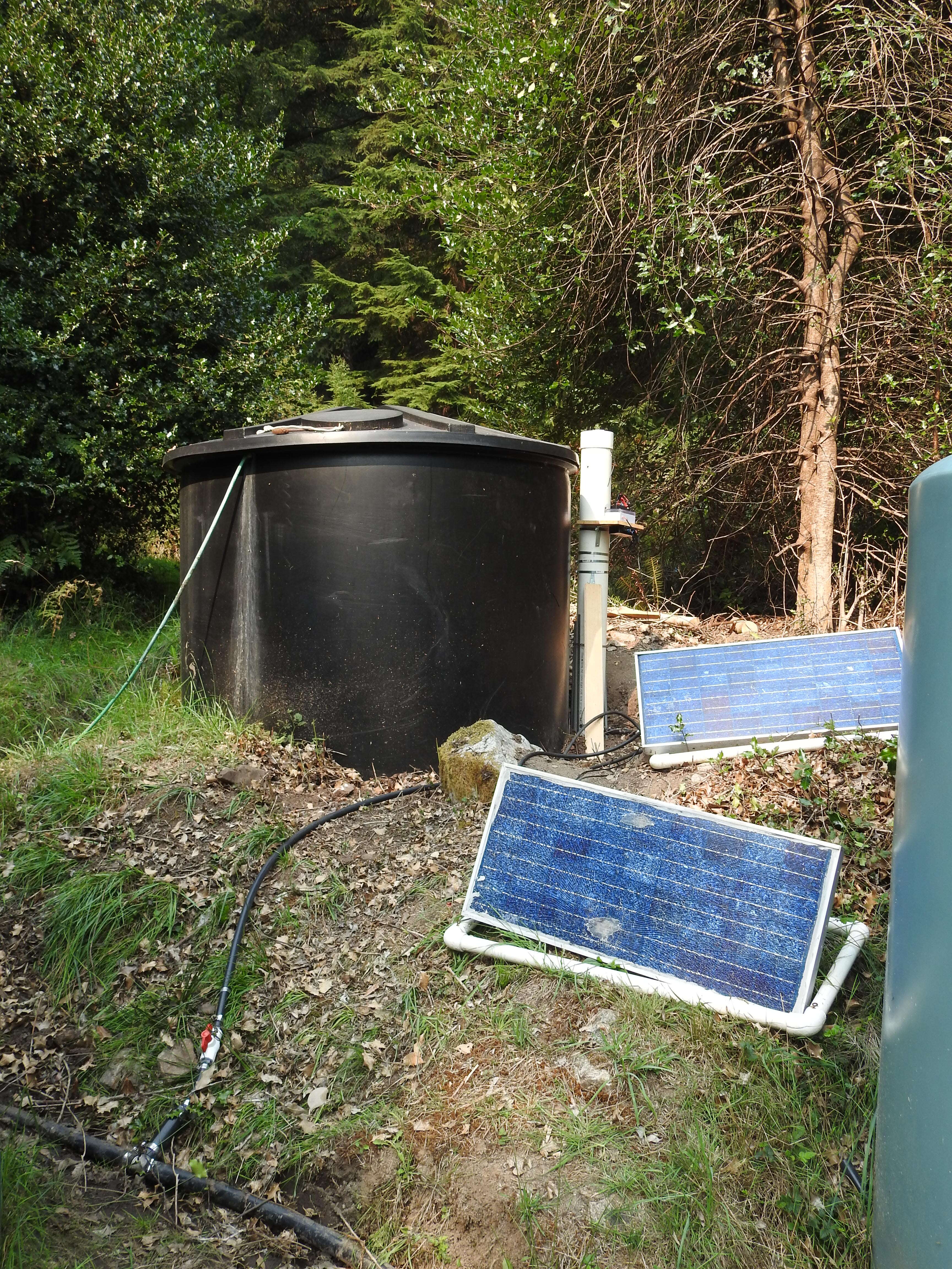
Thanks Pete. I wanted to keep my explanation simple for the example. Actually the sensor isn’t physically moved. The white sensor tank is next to the black tank only for support. If you look at the picture you’ll see the tank is connected to the black ABS line that runs in the front of the picture. That line is connected to all four tanks. So when three of the tanks are shutoff, the white tank is connected in series to ONLY the tank that is turned on, so the sensor isn’t physically moved. I’m not interested in the volume of water in each tank, just how much use there is. If the water level decreases dramatically it tells us something’s wrong and some action on our part has to be taken - either to look for a break in the line or to warn people to use less water.
I’ve combined the above sketch with the one of my earlier receiver sketches. I’ve tested it out and it… sort of… works… First thing I notice is I have to hit the button twice before it will change from the previous reading. Second, as Pete predicted, it shows the value at the moment the button is pressed, it does not show updating values. To see the updated value you have to hit the button twice. I have a feeling the code could probably be streamlined a bit… any suggestions on how to fix the two previously mentioned problems?
/*
* For this example you'll need the following library:
*  *
* 1) Arduino-LiquidCrystal-I2C-library: https://github.com/fdebrabander/Arduino-LiquidCrystal-I2C-library
*
* 2) Blynk Library: https://github.com/blynkkk/blynk-library
*
* Conncetions:
* D1 -> SCL of I2C LCD
* D2 -> SDA of I2C LCD
* D3 -> Out of DHT11/22
*
*/
#include <LoRa.h>
#define BLYNK_PRINT Serial
#include <SPI.h>
#include <ESP8266WiFi.h>
#include <BlynkSimpleEsp8266.h>
#include <Wire.h>
#include <LiquidCrystal_I2C.h>
LiquidCrystal_I2C lcd(0x27, 16, 2);

#define I2C_SDA D3 //redefining I2C pins as D1 is needed by LoRa unit
#define I2C_SCL D4

#define ss 15
#define rst 16
#define dio0 2

const int ledPin = D1; //warning light that water has dropped beyone preset level
char auth[] = "xxxxxxxxxxxxxxxxxxxxxx"; //Enter the Auth code which was send by Blink
char ssid[] = "xxxxxxxxxxxxxxxxxxxxxxxx2";  //Enter your WIFI Name
char pass[] = "xxxxxxxxxxxxxxxx";  //Enter your WIFI Password

void setup()
{
pinMode(ledPin,OUTPUT);
Wire.pins(D3, D4);
Serial.begin(9600);

lcd.begin();   // iInit the LCD for 16 chars 2 lines
lcd.backlight();   // Turn on the backligt (try lcd.noBaklight() to turn it off)
delay (1000);
Blynk.begin(auth, ssid, pass);

Serial.println("LoRa Sender");
LoRa.setPins(ss, rst, dio0);
if (!LoRa.begin(433E6))
  {
Serial.println("Starting LoRa failed!");
delay(100);
while (1);
  }
Serial.println("LoRa Started");
lcd.clear();
lcd.print("Waiting");
LoRa.setSpreadingFactor(10);
LoRa.setSignalBandwidth(62.5E3);
LoRa.crc();
}

void loop()
{

Blynk.run(); // Initiates Blynk

delay(1000);
  }
BLYNK_WRITE(V1) { // Segmented Switch
switch (param.asInt()){

    case 1: {
int packetSize = LoRa.parsePacket();
int targetDistance = LoRa.parseInt();
int tankOne = (targetDistance);
if (packetSize)
{
Blynk.virtualWrite(V0, tankOne);  // To Display Widget
  lcd.setCursor(0,0); //First line
  lcd.print("water is down");
  lcd.setCursor(0,1); //Second line
  lcd.print(tankOne);
  lcd.print(" inches");
}
//Alarm LED on receiving unit for tank One
if (targetDistance <= 25 )
      {
digitalWrite(ledPin,LOW);
      }
      else
      {
digitalWrite(ledPin,HIGH);
      }
break;
      }

    case 2: {
int packetSize = LoRa.parsePacket();
int targetDistance = LoRa.parseInt();
int tankTwo = (targetDistance - 4);
if (packetSize)
{
Blynk.virtualWrite(V0, tankTwo);  // To Display Widget
  lcd.setCursor(0,0); //First line
  lcd.print("water is down");
  lcd.setCursor(0,1); //Second line
  lcd.print(tankTwo);
  lcd.print(" inches");
}
  //Alarm LED on receiving unit for tank 2
      if (targetDistance <= 21 )
      {
  digitalWrite(ledPin,LOW);
      }
      else
      {
  digitalWrite(ledPin,HIGH);
      }
  break;
      }

  case 3: {
  int packetSize = LoRa.parsePacket();
  int targetDistance = LoRa.parseInt();
  int tankThree = (targetDistance - 8);
   if (packetSize)
   {
  Blynk.virtualWrite(V0, tankThree);  // To Display Widget
  lcd.setCursor(0,0); //First line
  lcd.print("water is down");
  lcd.setCursor(0,1); //Second line
  lcd.print(tankThree);
  lcd.print(" inches");
   }
  //Alarm LED on receiving unit for tank 3
      if (targetDistance <= 17 )
      {
  digitalWrite(ledPin,LOW);
      }
      else
      {
  digitalWrite(ledPin,HIGH);
      }
  break;
      }

    case 4: {
  int packetSize = LoRa.parsePacket();
  int targetDistance = LoRa.parseInt();
  int tankFour = (targetDistance - 12);
   if (packetSize)
   {
  Blynk.virtualWrite(V0, tankFour);  // To Display Widget
  lcd.setCursor(0,0); //First line
  lcd.print("water is down");
  lcd.setCursor(0,1); //Second line
  lcd.print(tankFour);
  lcd.print(" inches");
   }
  //Alarm LED on receiving unit for Ttank 4
      if (targetDistance <= 13 )
      {
  digitalWrite(ledPin,LOW);
      }
      else
      {
  digitalWrite(ledPin,HIGH);
      }
  break;
      }
        }
}
You have to read this
https://docs.blynk.io/en/legacy-platform/legacy-articles/keep-your-void-loop-clean
Thanks John, a very interesting article. I’ve learned something from it. Although I’m not sure it will help me solve this problem as I’m not getting an sort of Flooding or Device off line error.
Yes, it might not solve your problem, but your sketch has to be error free to work properly
You need to start by adding a timer, which calls a finctio once every secong, and remove the delay from your void loop. You need to add timer.run to your void loop, to make the timer work.
This is excplained in the “keep your void loop clean” article.
Call the timed function “take a reading()”
Declare a global integer variable called “tank_to_read” and another called “adjustment”
Remove everything from BLYNK_WRITE(V1) and replace it with this:
BLYNK_WRITE(V1)  // Segmented Switch
{
  tank_to_read = param.asInt();

  switch (tank_to_read)
  {
    case 1:
   {
     adjustment = 0
     break;
   }

    case 2:
   {
     adjustment = 4
     break;
   }

    case 3:
   {
     adjustment = 8
     break;
   }

    case 4:
   {
     adjustment = 12
     break;
   }
}
Your take a reading() function should then look something like this…
void take a reading()
{
  int packetSize = LoRa.parsePacket();
  int reading = LoRa.parseInt();
  int adjusted_reading = (reading - adjustment);
  int warning_level = 25 - adjustment;

  Serial.print("Selected tank = ");
  Serial.println(tank_to_read);

  Serial.print("Actual reading = ");
  Serial.println(reading);

  Serial.print("Adjustment factor = ");
  Serial.println(adjustment);

  Serial.print("Adjusted reading = ");
  Serial.println(adjusted_reading);


  if (packetSize)
  {
    Blynk.virtualWrite(V0, adjusted_reading);  // To Display Widget
    lcd.setCursor(0,0); //First line
    lcd.print("water is down");
    lcd.setCursor(0,1); //Second line
    lcd.print(adjusted_reading);
    lcd.print(" inches");
   }
   //Alarm LED on receiving unit for tank 3
   if (reading <= warning_level )
   {
      digitalWrite(ledPin,LOW);
   }
   else
   {
      digitalWrite(ledPin,HIGH);
   }
}
This code is obviously untested, but I’ve added enough debug information to help you identify any logic errors.
As you can hopefully see, I’ve removed all of the duplication and used parameters to make the adjustments rather than hard coding them.
Pete.
As always, I’m in your debt, Pete. Without your help when I get stuck, I’d be really lost. I’ll give it a try in the next day or so and report back.
Thanks
Jeff
Hi Pete:
Got around to testing it. A few missing ";"s and some other minor things - put in to test me! It appears to work great! Nice Job!!!
Couldn’t have done it without you. Hopefully it will help some others. I’ll add a couple of bells and whistles (notification and SuperChart, and then consider it done.
Thanks again.
Jeff
 * For this example you'll need the following library:
 *  *
 * 1) Arduino-LiquidCrystal-I2C-library: https://github.com/fdebrabander/Arduino-LiquidCrystal-I2C-library
 *
 * 2) Blynk Library: https://github.com/blynkkk/blynk-library
 *
 * Conncetions:
 * D1 -> SCL of I2C LCD
 * D2 -> SDA of I2C LCD
 * D3 -> Out of DHT11/22
 *
 */
#include <LoRa.h>
#define BLYNK_PRINT Serial
#include <SPI.h>
#include <ESP8266WiFi.h>
#include <BlynkSimpleEsp8266.h>
#include <Wire.h>
#include <LiquidCrystal_I2C.h>
LiquidCrystal_I2C lcd(0x27, 16, 2);

#define I2C_SDA D3 //redefining I2C pins as D1 is needed by LoRa unit
#define I2C_SCL D4

#define ss 15
#define rst 16
#define dio0 2

int adjustment;
int tank_to_read;

const int ledPin = D1; //warning light that water has dropped beyone preset level
char auth[] = "ZFiawkv0a-UnC_tXeO3Ir0n_FRhEXy1v"; //Enter the Auth code which was send by Blink
char ssid[] = "kuggle's_condo_2";  //Enter your WIFI Name
char pass[] = "jakesnak";  //Enter your WIFI Password

BlynkTimer timer;

void setup()
{

timer.setInterval(1000L,take_a_reading);

pinMode(ledPin,OUTPUT);
Wire.pins(D3, D4);

Serial.begin(9600);

lcd.begin();   // iInit the LCD for 16 chars 2 lines
lcd.backlight();   // Turn on the backligt (try lcd.noBaklight() to turn it off)
delay (1000);
Blynk.begin(auth, ssid, pass);

Serial.println("LoRa Sender");
LoRa.setPins(ss, rst, dio0);
if (!LoRa.begin(433E6))
  {
Serial.println("Starting LoRa failed!");
delay(100);
while (1);
  }
Serial.println("LoRa Started");
lcd.clear();
lcd.print("Waiting");
LoRa.setSpreadingFactor(10);
LoRa.setSignalBandwidth(62.5E3);
LoRa.crc();
}

void take_a_reading()
{
  int packetSize = LoRa.parsePacket();
  int reading = LoRa.parseInt();
  int adjusted_reading = (reading - adjustment);
  int warning_level = 25 - adjustment;

  Serial.print("Selected tank = ");
  Serial.println(tank_to_read);

  Serial.print("Actual reading = ");
  Serial.println(reading);

  Serial.print("Adjustment factor = ");
  Serial.println(adjustment);

  Serial.print("Adjusted reading = ");
  Serial.println(adjusted_reading);


  if (packetSize)
  {
    Blynk.virtualWrite(V0, adjusted_reading);  // To Display Widget
    lcd.setCursor(0,0); //First line
    lcd.print("water is down");
    lcd.setCursor(0,1); //Second line
    lcd.print(adjusted_reading);
    lcd.print(" inches");
   }
   //Alarm LED on receiving unit for tank 3
   if (reading <= warning_level )
   {
      digitalWrite(ledPin,LOW);
   }
   else
   {
      digitalWrite(ledPin,HIGH);
   }
}


void loop()
{

Blynk.run(); // Initiates Blynk
timer.run();

  }

BLYNK_WRITE(V1)
{
 tank_to_read = param.asInt();

  switch (tank_to_read)
  {
    case 1:
   {
     adjustment = 0;
     break;
   }

    case 2:
   {
     adjustment = 4;
     break;
   }

    case 3:
   {
     adjustment = 8;
     break;
   }

    case 4:
   {
     adjustment = 12;
     break;
   }
}


 }
Excellent, glad it (sort of) worked!
I wrote the example code on my iPad, so it’s a bit tricky to spot the syntax errors, and I did say “should then look something like this” 
Pete.
I don’t expect to you to give it to me on a platter (although you sort of did), but it was enough for me to understand what you did, and so any small errors in typing etc were easy for me to spot. Thanks again for the help.
Until next time.
Keep Safe (new virus???)
Jeff
one thought. At some point I should probably consider moving over to Blink 2.0. I’m hoping that it won’t require a lot of changes in the sketch.
Jeff
Thanks John.
1 Like
You won’t be able to use the Edgent features such as WiFi provisioning and OTA updates with your hardware, so the migration will be a simple case of setting-up a template in Blynk IoT and defining the datastreams then creating a device based on that template, adding your Template ID to the top of your existing code, replacing your auth token with the Blynk IoT token.
You’ll need to have the latest Blynk library installed, whereas you should be using the Legacy 0.6.1 library at the moment.
Pete.
Thanks Pete.