DigitalPin toggle error

Recently i try to interact with blynk 2.0 for my smart home automation system.
I used 8 virtual pin (V1-V8) and connect it with (D0-D7) but i can only toggle D0,D1 and D2.
Others pin are by default high and D3,D5 is Low. Please help me to solve problems
Here is my code for same

#define BLYNK_TEMPLATE_ID ""
#define BLYNK_DEVICE_NAME ""

#define BLYNK_FIRMWARE_VERSION        "0.1.0"

#define BLYNK_PRINT Serial
//#define BLYNK_DEBUG

#define APP_DEBUG

// Uncomment your board, or configure a custom board in Settings.h
//#define USE_SPARKFUN_BLYNK_BOARD
 #define USE_NODE_MCU_BOARD
//#define USE_WITTY_CLOUD_BOARD

#include "BlynkEdgent.h"

#define RelayPin1 16  //D0
#define RelayPin2 5 //D1
#define RelayPin3 4 //D2
#define RelayPin4 0 //D3
#define RelayPin5 2  //D4
#define RelayPin6 14 //D5
#define RelayPin7 12 //D6
#define RelayPin8 13 //D7

BLYNK_WRITE(V1)
{
  int pinValue = param.asInt(); // assigning incoming value from pin V1 to a variable
  {
    if(param.asInt() == 1) 
    { 
      digitalWrite(RelayPin1, LOW);
      Serial.println("1ON");
    }
    else
    {
      digitalWrite(RelayPin1, HIGH);
      Serial.println("1OFF");
    }
  } 
}

BLYNK_WRITE(V2)
{
  int pinValue = param.asInt(); // assigning incoming value from pin V1 to a variable
  {
    if(param.asInt() == 1) 
    { 
      digitalWrite(RelayPin2, LOW);
      Serial.println("2ON");
    }
    else
    {
      digitalWrite(RelayPin2, HIGH);
      Serial.println("2OFF");
    }
  } 
}

BLYNK_WRITE(V3)
{
  int pinValue = param.asInt(); // assigning incoming value from pin V1 to a variable
  {
    if(param.asInt() == 1) 
    { 
      digitalWrite(RelayPin3, LOW);
      Serial.println("3ON");
    }
    else
    {
      digitalWrite(RelayPin3, HIGH);
      Serial.println("3OFF");
    }
  } 
}

BLYNK_WRITE(V4)
{
  int pinValue = param.asInt(); // assigning incoming value from pin V1 to a variable
  {
    if(param.asInt() == 1) 
    { 
      digitalWrite(RelayPin4, LOW);
      Serial.println("4ON");
    }
    else
    {
      digitalWrite(RelayPin4, HIGH);
      Serial.println("4FF");
    }
  } 
}
BLYNK_WRITE(V5)
{
  int pinValue = param.asInt(); // assigning incoming value from pin V1 to a variable
  {
    if(param.asInt() == 1) 
    { 
      digitalWrite(RelayPin5, LOW);
      Serial.println("5ON");
    }
    else
    {
      digitalWrite(RelayPin5, HIGH);
      Serial.println("5FF");
    }
  } 
}

BLYNK_WRITE(V6)
{
  int pinValue = param.asInt(); // assigning incoming value from pin V1 to a variable
  {
    if(param.asInt() == 1) 
    { 
      digitalWrite(RelayPin6, LOW);
      Serial.println("6ON");
    }
    else
    {
      digitalWrite(RelayPin6, HIGH);
      Serial.println("6FF");
    }
  } 
}

BLYNK_WRITE(V7)
{
  int pinValue = param.asInt(); // assigning incoming value from pin V1 to a variable
  {
    if(param.asInt() == 1) 
    { 
      digitalWrite(RelayPin7, LOW);
      Serial.println("7ON");
    }
    else
    {
      digitalWrite(RelayPin7, HIGH);
      Serial.println("7FF");
    }
  } 
}

BLYNK_WRITE(V8)
{
  int pinValue = param.asInt(); // assigning incoming value from pin V1 to a variable
  {
    if(param.asInt() == 1) 
    { 
      digitalWrite(RelayPin8, LOW);
      Serial.println("8ON");
    }
    else
    {
      digitalWrite(RelayPin8, HIGH);
      Serial.println("8FF");
    }
  } 
}


void setup()
{
  Serial.begin(115200);
  delay(100);
  
  pinMode(RelayPin1, OUTPUT);
  pinMode(RelayPin2, OUTPUT);
  pinMode(RelayPin3, OUTPUT);
  pinMode(RelayPin4, OUTPUT);
  pinMode(RelayPin5, OUTPUT);
  pinMode(RelayPin6, OUTPUT);
  pinMode(RelayPin7, OUTPUT);
  pinMode(RelayPin8, OUTPUT);
  pinMode(LED_BUILTIN, OUTPUT);

  //During Starting all Relays should TURN OFF
  digitalWrite(RelayPin1, HIGH);
  digitalWrite(RelayPin2, HIGH);
  digitalWrite(RelayPin3, HIGH);
  digitalWrite(RelayPin4, HIGH);
  digitalWrite(RelayPin5, HIGH);
  digitalWrite(RelayPin6, HIGH);
  digitalWrite(RelayPin7, HIGH);
  digitalWrite(RelayPin8, HIGH);
  BlynkEdgent.begin();
}

void loop() {
    {
    if (WiFi.status() == WL_CONNECTED)
   
        {
            digitalWrite(LED_BUILTIN, LOW);
            
                    }
        else{
          digitalWrite(LED_BUILTIN, HIGH);
        }
   }
  BlynkEdgent.run();
}

@Pu00112 please edit your post, using the pencil icon at the bottom, and add triple backticks at the beginning and end of your code.
Triple backticks look like this:
```

Pete.

Yes sir i have edited post

First of all, there are some errors in the comments regarding pin numbering…

If you are using one of the common NodeMCUs that has only one onboard LED then this is connected to GPIO2, which you are using a relay output.
If it’s a NodeMCU with two LEDs then the second on is attached to GPIO16, which is also in use as a relay output.

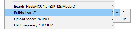
Which one is treated as LED_BUILTIN will depend on the option you chose when you compiled your code in the IDE…
image

You should also read this, about the suitability of the pins you are using…

As you’ll see, the NodeMCU doesn’t have enough suitable pins for your project, and you’d be better using an ESP32.

Pete.

Sir i have edited code as you said now only D3 pin is not working and D6,D7 pins are default HIGH when i toggle 2 pins they get low for some millisecond and get HIGH. But i can see in serial monitor about on off status of all pins


#define BLYNK_TEMPLATE_ID "TMPLtwf6YfIC"
#define BLYNK_DEVICE_NAME "Room"

#define BLYNK_FIRMWARE_VERSION        "0.1.0"

#define BLYNK_PRINT Serial
//#define BLYNK_DEBUG

#define APP_DEBUG

// Uncomment your board, or configure a custom board in Settings.h
//#define USE_SPARKFUN_BLYNK_BOARD
 #define USE_NODE_MCU_BOARD
//#define USE_WITTY_CLOUD_BOARD

#include "BlynkEdgent.h"

#define RelayPin1 16  //D0
#define RelayPin2 5 //D1
#define RelayPin3 4 //D2
#define RelayPin4 0 //D3
#define RelayPin5 2  //D4
#define RelayPin6 14 //D5
#define RelayPin7 12 //D6
#define RelayPin8 13 //D7

BLYNK_WRITE(V1)
{
  int pinValue = param.asInt(); // assigning incoming value from pin V1 to a variable
  {
    if(param.asInt() == 1) 
    { 
      digitalWrite(RelayPin1, LOW);
      Serial.println("1ON");
    }
    else
    {
      digitalWrite(RelayPin1, HIGH);
      Serial.println("1OFF");
    }
  } 
}

BLYNK_WRITE(V2)
{
  int pinValue = param.asInt(); // assigning incoming value from pin V1 to a variable
  {
    if(param.asInt() == 1) 
    { 
      digitalWrite(RelayPin2, LOW);
      Serial.println("2ON");
    }
    else
    {
      digitalWrite(RelayPin2, HIGH);
      Serial.println("2OFF");
    }
  } 
}

BLYNK_WRITE(V3)
{
  int pinValue = param.asInt(); // assigning incoming value from pin V1 to a variable
  {
    if(param.asInt() == 1) 
    { 
      digitalWrite(RelayPin3, LOW);
      Serial.println("3ON");
    }
    else
    {
      digitalWrite(RelayPin3, HIGH);
      Serial.println("3OFF");
    }
  } 
}

BLYNK_WRITE(V4)
{
  int pinValue = param.asInt(); // assigning incoming value from pin V1 to a variable
  {
    if(param.asInt() == 1) 
    { 
      digitalWrite(RelayPin4, LOW);
      Serial.println("4ON");
    }
    else
    {
      digitalWrite(RelayPin4, HIGH);
      Serial.println("4FF");
    }
  } 
}
BLYNK_WRITE(V5)
{
  int pinValue = param.asInt(); // assigning incoming value from pin V1 to a variable
  {
    if(param.asInt() == 1) 
    { 
      digitalWrite(RelayPin5, LOW);
      Serial.println("5ON");
    }
    else
    {
      digitalWrite(RelayPin5, HIGH);
      Serial.println("5FF");
    }
  } 
}

BLYNK_WRITE(V6)
{
  int pinValue = param.asInt(); // assigning incoming value from pin V1 to a variable
  {
    if(param.asInt() == 1) 
    { 
      digitalWrite(RelayPin6, LOW);
      Serial.println("6ON");
    }
    else
    {
      digitalWrite(RelayPin6, HIGH);
      Serial.println("6FF");
    }
  } 
}

BLYNK_WRITE(V7)
{
  int pinValue = param.asInt(); // assigning incoming value from pin V1 to a variable
  {
    if(param.asInt() == 1) 
    { 
      digitalWrite(RelayPin7, LOW);
      Serial.println("7ON");
    }
    else
    {
      digitalWrite(RelayPin7, HIGH);
      Serial.println("7FF");
    }
  } 
}

BLYNK_WRITE(V8)
{
  int pinValue = param.asInt(); // assigning incoming value from pin V1 to a variable
  {
    if(param.asInt() == 1) 
    { 
      digitalWrite(RelayPin8, LOW);
      Serial.println("8ON");
    }
    else
    {
      digitalWrite(RelayPin8, HIGH);
      Serial.println("8FF");
    }
  } 
}


void setup()
{
  Serial.begin(115200);
  delay(100);
  
  pinMode(RelayPin1, OUTPUT);
  pinMode(RelayPin2, OUTPUT);
  pinMode(RelayPin3, OUTPUT);
  pinMode(RelayPin4, OUTPUT);
  pinMode(RelayPin5, OUTPUT);
  pinMode(RelayPin6, OUTPUT);
  pinMode(RelayPin7, OUTPUT);
  pinMode(RelayPin8, OUTPUT);

  //During Starting all Relays should TURN OFF
  digitalWrite(RelayPin1, HIGH);
  digitalWrite(RelayPin2, HIGH);
  digitalWrite(RelayPin3, HIGH);
  digitalWrite(RelayPin4, HIGH);
  digitalWrite(RelayPin5, HIGH);
  digitalWrite(RelayPin6, HIGH);
  digitalWrite(RelayPin7, HIGH);
  digitalWrite(RelayPin8, HIGH);
  BlynkEdgent.begin();
}

void loop() {
  BlynkEdgent.run();
}

Do you have your app widgets configured correctly (Switch rather than Push)?

What does the #if defined(USE_NODE_MCU_BOARD) section of your Settings.h tab look like?

Pete.

Yes sir i have configure widgets as switch
image

here is my settings.h code

#if defined(USE_NODE_MCU_BOARD)

  #warning "NodeMCU board selected"

  // Example configuration for NodeMCU v1.0 Board
  #define BOARD_BUTTON_PIN            0
  #define BOARD_BUTTON_ACTIVE_LOW     true

  #define BOARD_LED_PIN_R             D8
  #define BOARD_LED_PIN_G             D7
  #define BOARD_LED_PIN_B             D6
  #define BOARD_LED_INVERSE           false
  #define BOARD_LED_BRIGHTNESS        64

So what does this tell you about your GPIO0 (D0) and D6 & D7 pins?

You could use the latest version of the Edgent_ESP8266 Settings.h file from the Blynk GitHub site, but you’re still trying to do too much with the hardware you have.

Pete.