I am trying to activate a digital button when the value of a virtual display is a certain value.
I am using an ESP8266 12e to connect to the Blynk app. I am using an iPhone 11pro running iOS 14.0.1.
I upload the values to the Blynk app and they show up on the virtual display set to input V5 and refresh = Push.
When the uploaded values they change on the virtual display and Superchart.
However when I try to capture when the virtual display updates and use that value to activate the digital button (set to switch) nothing happens.
Here is my code ( I have taken some out because I have the user put their information (pass,ssid)in and it is stored and retrieved form EEPROM.
If V5 is a Value Display or Labelled Value display then it won’t trigger BLYNK_WRITE(V5), but your code triggered by BLYNK_WRITE(V5) would print a message which implies that V5 is actually a skider widget attached to pin V1… Serial.print("V1 Slider value is: ");
The BLYNK_WRITE(V5) callback then goes on to call non-existent functions called turnOnFiller() or turnOffFiller() but your turnOnButton() and turnOffButton() functions are never called.
I don’t know how much of this is down to you having hacked the code around before posting it here, but as it stands it makes no sense.
Maybe you should start by explaining in detail which widgets you have in your app and which pins they are connected to, and posting code that at least compiles correctly.
I have a Digital Button (PUSH) connected to GP14(LED) on an ESP8266-12e which when I push it activates that pin.
I PUSH values to the app from the ESP to V5.
I have a Slider with the output to V5. It changes values to correspond to the PUSH input to V5.
I have changed my code in original post to try to show what I am trying to do.
The code compiles good and most everything works ok except I can’t get the
BLYNK_WRITE(V5) to work.
I am trying to have the change n the slider value activate the Digital button.
I would prefer to use a SuperChart to be the trigger mechanism.
I can post all of my code if you would like but like I said it is just getting people to input their said and pass and store it and then retrieve it. That all works fine.
Your revised code doesn’t compile, for a number of reasons…
you have an unwanted closing curly bracket in your void setup, between led1.off(); and Blynk.begin(auth, ssid, pass);
the auth, ssid and pass declarations are missing
In addition, you say that you:
GPIO14 = D5, and you are referencing the pin as D5 in your code and assigning it the rather confusing pseudonym of LED. LED is being in initialised as an OUTPUT pin, but if it has a physical pushbutton attached to it then it needs to be initialised as an INPUT pin and either have an interrupt attached to it, or use a timer to poll the pin looking for a change of state (button pushed).
I suspect what you actually mean is that you have a widget switch, in pushbutton mode, attached to Digital Pin 5
Whether you also have a physical LED attached to the NodeMCU’s pin D5 and either GND opr VCC is anybody’s guess.
In your app you have an LED widget attached to virtual pin V1 and you’ve given this the pseudonym of led1
When the BLYNK_WRITE(V5) callback is triggered when the value of the slider widget attached to virtual pin V5 changes, it calls either turnOnFiller() or turnOffFiller().
These functions try to do a digitalWrite to the pin you’re referencing as LED which is pin D5 (GPIO14) on your NodeMCU and this is where you say you have a switch attached.
My guess is that these functions should actually be doing a virtualWrite to the LED widget that you’re referencing as led1 (attached to virtual pin V1).
However, you need to be aware that although Blynk.virtualWrite(led1,0) will turn the LED widget off, Blynk.virtualWrite(led1,1) will turn the LED widget on at it’s lowest value, on a scale of 0-255. If you want to turn the widget LED on at maximum brightness you should use Blynk.virtualWrite(led1,255)
If you are actually attaching a Blynk widget switch to Pin D5 then I’d suggest that you don’t do this, instead you should attach it to a virtual pin.
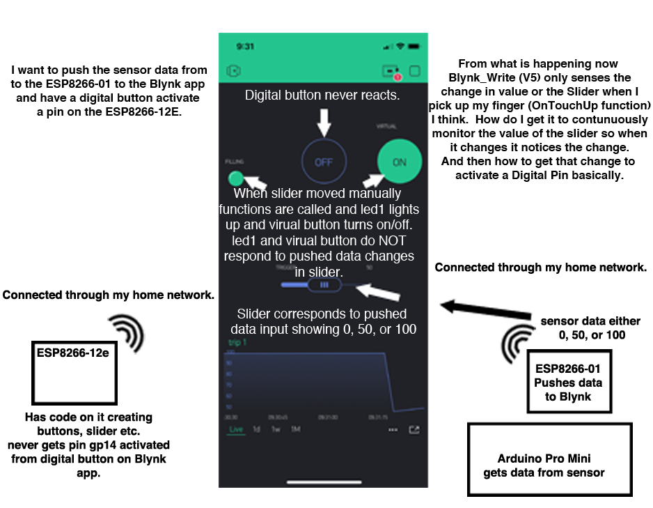
So I have been working on this and I have created a drawing of what I have and what I want to do.
To be clear:
I have an ESP8266-01 connected to an Arduino Pro Mini which has a sensor attached to it. The Pro checks the sensor every 2 hours and hands it off the the ESP. The ESP connects to my local wifi and sends the data to ThingSpeak and then Pushes it to the Blynk app on V5. The data is either 0, 50, or 100.
On the Blynk app I have one device, an ESP8266. I also have a Slider widget with output V5. This does respond to the pushed data moving to 0, 50, or 100.
There is also an led1 widget connected to input V1. There is also a Button set to switch with an output of V2. Both of these respond to my code when Blynk_Write(V5){} when I physically touch the Slider and move it to 0, 50, or 100. But when the incoming data changes the Slider the code is not called and the led and button do not respond. I am assuming that Blynk_Write(V5) is coded to (OnTouchUp).
In any case the Digital Button which is GP14 or D5 (assigned LED because of a post that did this, I know I don’t need it) never responds to the call to go HIGH or LOW. I know it is connected up correctly because when I physically touch the button in the app the led attached to pin GP14 Lights up.
It does not appear I can edit my original post and code.
But If anyone know. Is it possible to do what I want to do, which is;
TURN ON A PIN ON THE ESP-12E IN RESPONSE FROM DATA PUSHED TO BLYNK FROM AN ESP-01, BOTH BEING CONNECTED THROUGH THE SAME WIFI.
Okay, I think I now understand the issue.
Blynk Intentionally doesn’t trigger the BLYNK_WRITE(vPin) callback when you do a Blynk.digitalWrite(vPin,value) to the virtual pin.
This seems to be a sort of ‘self protection’ system to prevent a continuous loop occurring.
One way to handle this is to do virtualWrites to the widgets that you want to update, at the same time that you do a virtualWrite to the slider.
The alternative is to do a Blynk.syncVirtual(vPin) once you’ve written to the slider’s vPin. This will cause the server to trigger the BLYNK_WRITE(vPin) callback.
As far as the widget attached to the digital pin is concerned, I already covered this…
It works better if you post revised code in a new post within the topic, rather than going back and editing the original post.
I have placed Blynk.syncVirtual(V5); inside BLYNK_WIRTE(5){ code and now the incoming data is updated as it changes. Code then triggers led1 and virtual Button/pin V2 as Widget Slider changes value. This is great! However I don’t see how this can now be tied to the digitalPin(D5) or GP14 which is my ultimate goal. I have tried to BLYNK_WRITE(V2) at another place but this doesn’t seem to work. Can you point me to how I activate pin (D5) to V2’s state?
Again thanks for all your help.
So I went back and changed the Blynk.virtualWrite(V2) from the sensing ESP8266-01 to push either 1 or 0.
Then I tied that to a virtual Switch Widget set to push mode on V2. I then wrote this code on the ESP8266-12e which is the receiver.
BLYNK_WRITE(V2)

   {
    Blynk.syncVirtual(V2);

   int pinValue = param.asInt(); // Assigning incoming value from pin V5 to a variable
 Serial.print("Pin number: ");
 Serial.println(LED);
 Serial.print("Value read from Blynk ButtonPress: ");
Serial.println(pinValue);
 if (pinValue == 1) {
    digitalWrite(LED, HIGH); // Turn LED on.
  } else {
    digitalWrite(LED, LOW); // Turn LED off.
 }
and walls it works. If I push the virtual button it the LED attached to the GP14 pin on the 12e lights up and if I push the values on the from the sensor ESP the LED lights up.
I don’t like having the Blynk.syncVirtual(V2) all the time so I might put it inside a timer to only run for an hour every 23hrs. and have my sensor run in the middle of that. If I don’t have Blynk.syncVirtual(V2) in there the push button works but not the pushed data from the esp-01.
There is a strange thing though. When I connect the ESP8266-12e to the FTDI and run it this all works fine. However when I hook it up to my board which powers it with a 24v center tap transformer that is rectified and then reduced in voltage to 3.3vdc, the LED lights up when I tap the virtual button but when the pin is activated by the remote esp12e the LED doesn’t light up. I hooked the pin up to a amp meter and produces .1 mA when the button is physically push and .2/3 mA when the remotely activated. I am running it through a transistor because it wasn’t triggering in another way. Could there be too much amperage for the transistor. Or can anyone think of another reason for this weird behavior.
Anyway thanks for your help. If you think I need to change something please let me know.
In your previous set of code you were putting Blynk.syncVirtual(V5) inside the BLYNK_WRITE(V5) callback function.
Now you’re putting Blynk.syncVirtual(V2) inside the BLYNK_WRITE(V2) callback function.
I really don’t understand your logic for doing this.
Blynk.syncVirtual(V2) causes the BLYNK_WRITE(V2) callback function to be executed, so what you’re doing is risking an endless loop situation.
I introduced you to the idea of using the Blynk.syncVirtual(vPin) command to force the BLYNK_WRITE(vPin) function to be triggered when a different had written data to vPin elsewhere in your code (which wouldn’t automatically trigger the BLYNK_WRITE(vPin) callback).
You seem to have totally misunderstood this use of the Blynk.syncVirtual(vPin) command.
You’re now also talking about a ‘Sensor ESP’ and a ‘Receiver ESP’, which is a concept that was missing from your previous explanation as far as I can see.
If this is what you are doing then you need to use Bridge code, with two separate Auth codes and a Blynk bridge between the two.
As far as the hardware side of things are concerned, if you’re using bare ESP12 chips then they are quite sensitive to power issues. It’s generally much simpler to use a complete dev board rather than a bare chip. If size is an issue then the Wemos D1 Mini is not much bigger that the bare chip and the necessary smoothing and pull-up components.
I’m sorry you misunderstood me but in my drawing diagram I show two different ESPs. A -01 as a sensing unit and a12e the receiving unit. Sorry I wasn’t clear. I am away of the power currency issues as I was trying to use RF transmitter/receiver before and they are very sensitive to this. I will continue on with looking at Bridge mode etc.
Thanks again
Yes, I missed that - too busy trying to figure out the physical versus widget buttons/LEDs I guess.
Maybe a learning point would be to start with an overview of the project, it’s purpose and the hardware used. It’s also handy if you state whether things like switches and LEDS are physical objects or app widgets.
Thank you for all the info. I am now using Bridge widget and have the digital pin going HIGH when I want it to. Also sending info over to app for display. Wonderful. Can I use Webhooks Widget with IFTTT? I am now loading other sensor info to ThingSpeak and firing off IFTTT from there but it would be nicer to use just one interface.
Again thanks
Maybe you should explain more about what you want to achieve with (the now rather expensive) IFTTT service before we start guessing about what it is that you’re trying to do.
There are lots of posts on the forum about using IFTTT to update Blynk virtual pins, including how to avoid the pitfalls of Geo DNS.
So I am trying to use the Notifications Widget in Blynk instead of IFTTT. On the receiving ESP-12e I have included the following code but it doesn’t seem to push any notifications to my device (iPhone).
BLYNK_WRITE(V5)
{


   int pinValue = param.asInt(); // Assigning incoming value from pin V5 to a variable
 Blynk.virtualWrite(V5,pinValue);
 if(pinValue<-2){
  Blynk.notify("Your pool is dangerously low, try manually filling it with the button in your Blynk App");

 }
 else if(pinValue>35){
  Blynk.notify("Your pool is dangerously High, try manually filling it with the button in your Blynk App");
   }}
Any ideas on why this doesn’t work. I have looked at different examples and this seems to be how to do it.
What is your logic behind having this line in your code?
Also…
What type of widget is attached to V5?
Are you still using two devices and Bridge?
If so, is this code on the sending or the receiving device, and what pin(s) are you sending the data on?
If you add Serial.println(pinValue); immediately after int pinValue = param.asInt(); then what are you seeing in your serial monitor?
I am using bridge widget mode with two devices. ESP-01 (sending) and ESP-12e (receiving).
I have the code in the receiving ESP-12e as I said above. V5 is attached to a level widget with values 0-40. When I send the value over it is reflected in the level widget. My logic behind the code is that if the pinValue of V5 is above 35 I want to have a notification on the user’s phone and if the pinValue of V5 is below -2 a different notification will show up on the user’s phone. I have sent values above and below these to V5 and they appear on the level widget but there is no notification on the phone. Do I need to include any specific .h for this to work. I didn’t think so but … does this help explain things better?
get the incoming value from Pin V5 then immediately write that value back to V5. WHY?
Is the transmitting device sending data on pin V5?
If so, I think you would be better to attach your level widget to a different virtual pin, and write the incoming data to this as part of your BLYNK_WRITE(V5) callback.
This is post #17, and quite a lot of code has been posted “above”. If you’re referring to the code in post #15 then it would be useful if you stated that specifically.
It would also be useful if you answered each of the questions that I asked in post '16, as we still only have half of the picture.
Got everything working now. All notifications and digital/virtual writes and widgets. Going to try a camera (streaming video next).
Thanks again a lot!!!