#8 Simple AC Power Monitor (Using ACS712)
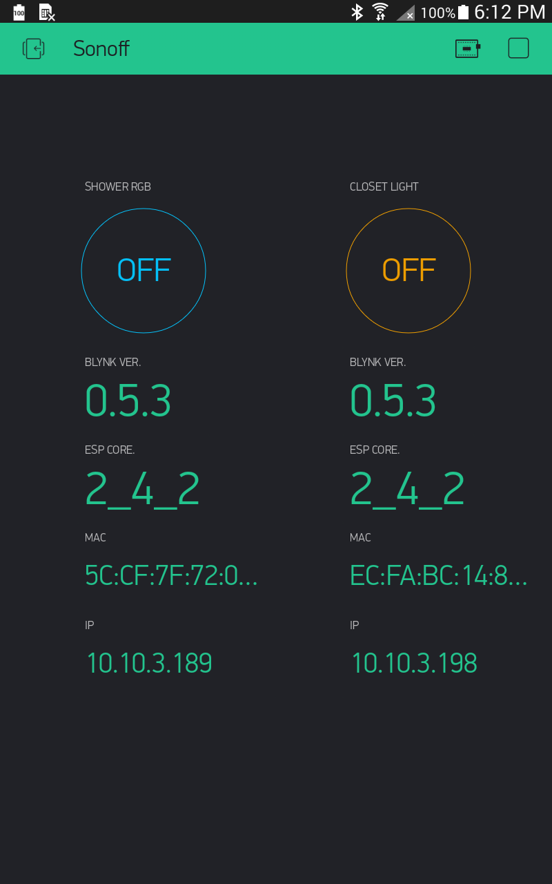
This is something I have running on my workbench… simply monitoring the power used by my computer system. So the current adjustments visible on the graph are the difference between my monitors being on or off.
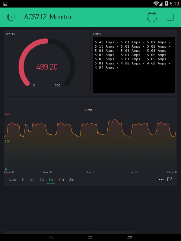
The shading is normal, but I am also using the gradient colour so that it goes from green at its lowest to red at its highest.
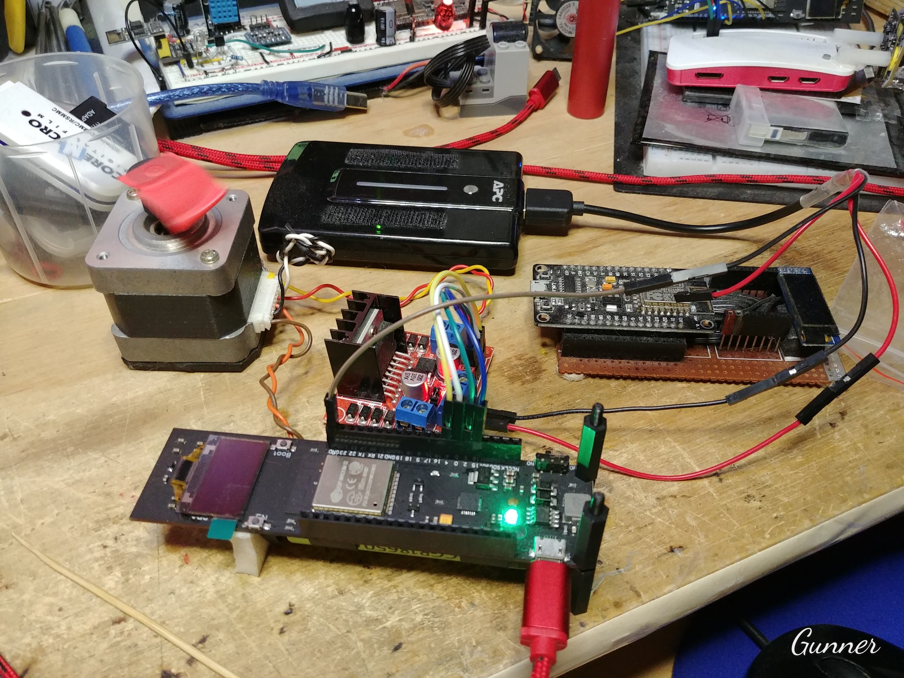
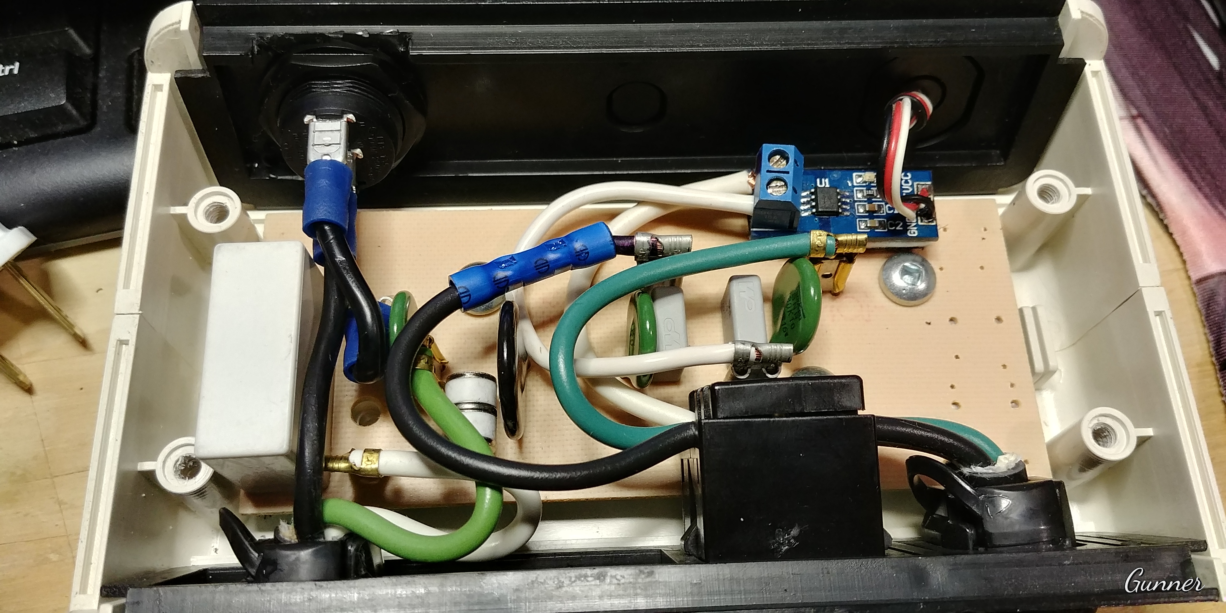
I have mounted my sensor in an old power tap / spike regulator box…
Not sure I would trust it to the full 15A ![]()
![]()
![]()
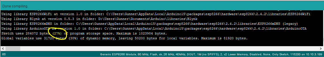
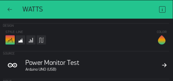
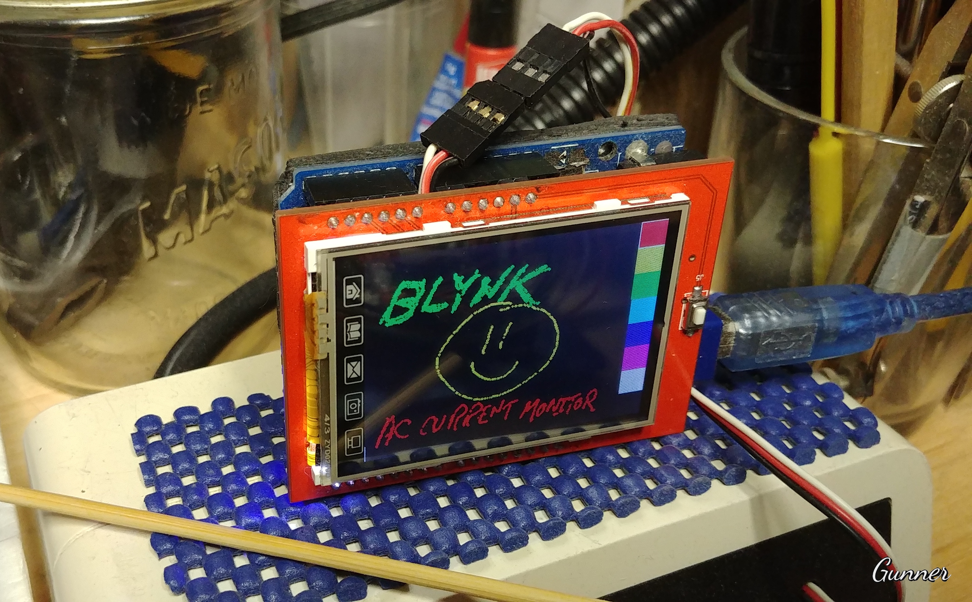
And yes, it is presently running on a lowly Arduino UNO using the USB Link ![]()
http://help.blynk.cc/how-to-connect-different-hardware-with-blynk/arduino/usb-serial

I “upgraded” my UNO that runs this AC Current Monitor. Since the UNO only needed one Analog port for the job… and that was all that is left over with these old LCD shields… I added the shield (no not including the merged-into-Blynk Paint code here ![]() ) but eventually I will instead use the display for actual AC current data… maybe even as a clock
) but eventually I will instead use the display for actual AC current data… maybe even as a clock ![]()
#include <BlynkSimpleStream.h> // For USB Link
//#include <ESP8266WiFi.h> // For WiFi with standalone ESP8266
//#include <BlynkSimpleEsp8266.h> // For WiFi with ESP8266 as shield for Arduino
char auth[] = "xxxxxxxxxx";
// char ssid[] = "xxxxxxxxxx"; // For WiFi
// char pass[] = "xxxxxxxxxx"; // For WiFi
// char server[] = "10.10.3.13"; // For WiFi - IP for your Local Server
// char server[] = "blynk-cloud.com"; // For WiFi - IP for your Local Server
const int sensorIn = A0;
int mVperAmp = 100; // use 100 for 20A Module and 66 for 30A Module
double Voltage = 0;
double VRMS = 0;
double AmpsRMS = 0;
BlynkTimer timer;
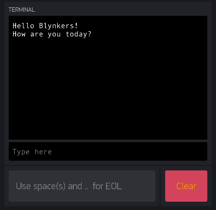
WidgetTerminal terminal(V1);
void setup() {
Serial.begin(9600); // USB Link
Blynk.begin(Serial, auth); // For USB Link
// WiFi.begin(ssid, pass); // For WiFi
// Blynk.config(auth, server, port); // For WiFi
// Blynk.connect(); // For WiFi
timer.setInterval(2000L, SensorRead);
}
void loop() {
Blynk.run();
timer.run();
}
void SensorRead() {
Voltage = getVPP();
VRMS = (Voltage / 2.0) * 0.707;
AmpsRMS = (VRMS * 1000) / mVperAmp;
Blynk.virtualWrite(V0, 0.9 * AmpsRMS * 110); // To Gauge Widget @ .9pf and 110vac
terminal.print(AmpsRMS); // To Terminal Widget
terminal.print(" Amps - ");
terminal.flush();
}
float getVPP() {
float result;
int readValue; //value read from the sensor
int maxValue = 0; // store max value here
int minValue = 1023; // store min value here
uint32_t start_time = millis();
while ((millis() - start_time) < 1500) { // sample for 1 Sec
readValue = analogRead(sensorIn); // see if you have a new maxValue
if (readValue > maxValue) {
maxValue = readValue; // record the maximum sensor value
}
if (readValue < minValue) {
minValue = readValue; // record the minimum sensor value
}
}
// Subtract min from max
result = ((maxValue - minValue) * 5.0) / 1023.0;
return result;
}
void ac_read() {
int rVal = 0;
int sampleDuration = 100; // 100ms
int sampleCount = 0;
unsigned long rSquaredSum = 0;
int rZero = 511; // For illustrative purposes only - should be measured to calibrate sensor.
uint32_t startTime = millis(); // take samples for 100ms
while ((millis() - startTime) < sampleDuration) {
rVal = analogRead(A0) - rZero;
rSquaredSum += rVal * rVal;
sampleCount++;
}
double voltRMS = 5.0 * sqrt(rSquaredSum / sampleCount) / 1024.0;
// x 1000 to convert volts to millivolts
// divide by the number of millivolts per amp to determine amps measured
// the 20A module 100 mv/A (so in this case ampsRMS = 10 * voltRMS
double ampsRMS = voltRMS * 10.0;
}


 )
)

 Well anyhow…
 -
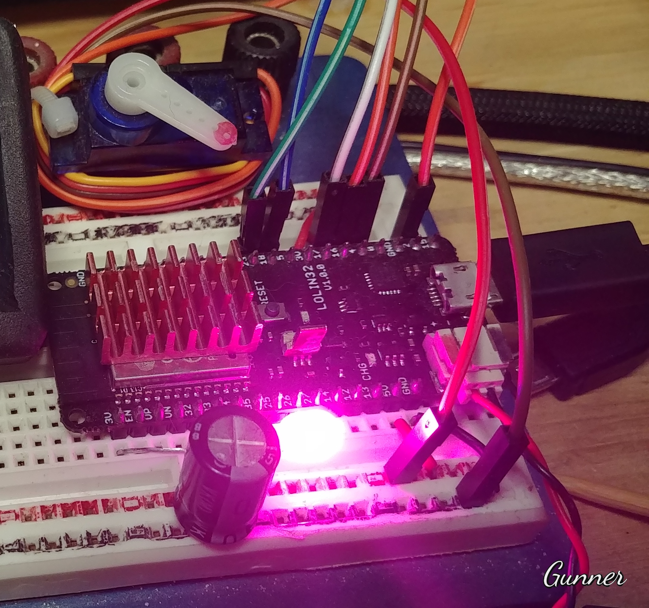
-  gling later and I found a few different websites that describe in more detail then I will get into here. How profoundly customisable the ESP32 GPIO pins are
 but the HEX data that shows the corresponding colour is useful)
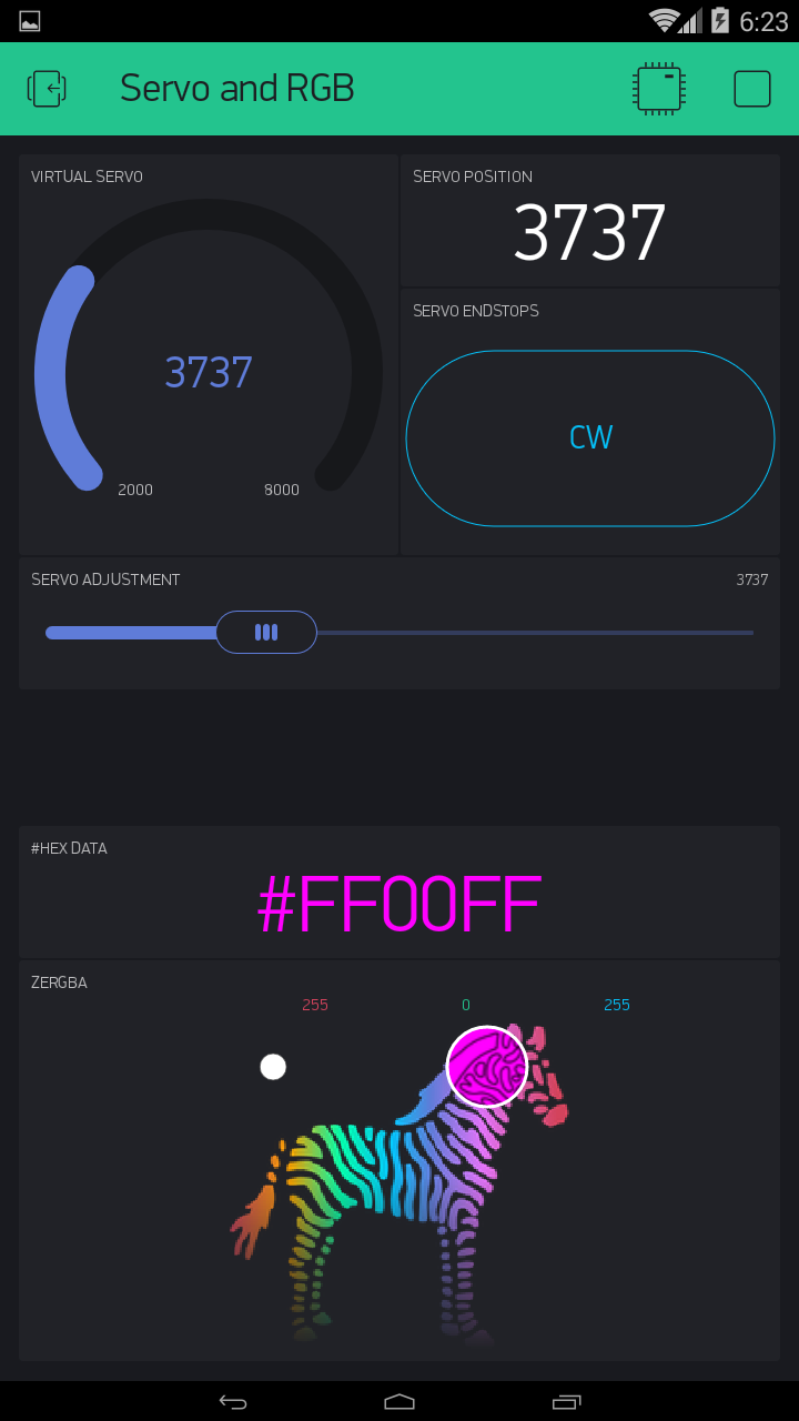

 )…
)…