Bridge: Syntax for 3 Way Bridge

Is a 3 way bridge, as defined below, possible and if so what is the syntax?

Device 1 updates 2 and 3.

Device 2 updates 1 and 3.

Device 3 updates 1 and 2.

Bridge is working for the 3 devices but each device is only updating one of the other devices rather than the required 2.

This is the syntax I am using for device 1 (similar, but different for the other 2 devices).

WidgetBridge bridge2(V31);        
WidgetBridge bridge3(V31);

void myfunction((){
  bridge2.virtualWrite(V30, value);               
  bridge3.virtualWrite(V30, value);
}

BLYNK_CONNECTED() { 
  bridge2.setAuthToken("device2token"); 
  bridge3.setAuthToken("device3token"); 
}

With this syntax, device 1 will update device 3 but not 2. It is consistent that any of the 3 devices will only update the last bridgeX in the sequence.

@Costas,
Today should be my “lucky day”, please check my working code :slight_smile:

-Device 1:

#define BLYNK_PRINT Serial    // Comment this out to disable prints and save space
#include <ESP8266WiFi.h>
#include <BlynkSimpleEsp8266.h>
#include <SimpleTimer.h> //Blynk
SimpleTimer timer;

// You should get Auth Token in the Blynk App.
// Go to the Project Settings (nut icon).
char auth[] = "TOKEN1";

// Your WiFi credentials.
// Set password to "" for open networks.
char localserver[16] = "XXX.XXX.X.X";          // Enter your IP details for the local server  RPI ZERO
char ssid[] = "XXXXXXXXX";                   // Your WiFi credentials.
char pass[] = "XXXXXXXXXXXXX";

bool isFirstConnect = true;
int slider;

WidgetBridge bridge2(V5);
WidgetBridge bridge3(V6);

BLYNK_CONNECTED() {
if (isFirstConnect) {
Blynk.syncAll();
Blynk.notify("Device 1 Starting!!!!");
isFirstConnect = false;
}
bridge2.setAuthToken("TOKEN2");// Token  2
bridge3.setAuthToken("TOKEN3");// Token  3
}

void setup()
{
  Serial.begin(115200);
  Serial.println("\n Starting");
  //Blynk.begin(auth, ssid, pass);              // normal Blynk Cloud server connection     
  //Blynk.config(auth, cloudserver);            // for Blynk's cloud server if WiFi already connected
  Blynk.begin(auth, ssid, pass, localserver);   // for a local server requiring WiFi connection
  int mytimeout = millis() / 1000;
  while (Blynk.connect(1000) == false) {        // wait here until connected to the server
    if((millis() / 1000) > mytimeout + 8){      // try to connect to the server for less than 9 seconds
      break;                                    // continue with the sketch regardless of connection to the server
    }
    }
  timer.setInterval(15000, reconnectBlynk); // check every 15 seconds if we are connected to the server
} 

void reconnectBlynk() // reconnect to server if disconnected, timer checks every 15 seconds
{                        
  if (!Blynk.connected()) {
    if(Blynk.connect()) {
      BLYNK_LOG("Reconnected");
    } else {
      BLYNK_LOG("Not reconnected");
    }
  }
}

BLYNK_WRITE(V1) 
{
 slider = param.asInt();
 bridge2.virtualWrite(V1, slider);
 bridge3.virtualWrite(V1, slider);
}


void loop()
{
 if (Blynk.connected()) {   // to ensure that Blynk.run() function is only called if we are still connected to the server
    Blynk.run();
} 
timer.run();
}

-Device 2:

#define BLYNK_PRINT Serial    // Comment this out to disable prints and save space
#include <ESP8266WiFi.h>
#include <BlynkSimpleEsp8266.h>
#include <SimpleTimer.h> //Blynk
SimpleTimer timer;

// You should get Auth Token in the Blynk App.
// Go to the Project Settings (nut icon).
char auth[] = "TOKEN2";

// Your WiFi credentials.
// Set password to "" for open networks.
char localserver[16] = "XXX.XXX.XXX.XXX";          // Enter your IP details for the local server  RPI ZERO
char ssid[] = "XXXXXXX";                   // Your WiFi credentials.
char pass[] = "XXXXXXXXXXXXX";

bool isFirstConnect = true;
int slider;

WidgetBridge bridge1(V4);
WidgetBridge bridge3(V6);

BLYNK_CONNECTED() {
if (isFirstConnect) {
Blynk.syncAll();
Blynk.notify("Device 2 Starting!!!!");
isFirstConnect = false;
}
bridge1.setAuthToken("TOKEN1");// Token  1
bridge3.setAuthToken("TOKEN3");// Token  3
}

void setup()
{
  Serial.begin(115200);
  Serial.println("\n Starting");
  //Blynk.begin(auth, ssid, pass);              // normal Blynk Cloud server connection     
  //Blynk.config(auth, cloudserver);            // for Blynk's cloud server if WiFi already connected
  Blynk.begin(auth, ssid, pass, localserver);   // for a local server requiring WiFi connection
  int mytimeout = millis() / 1000;
  while (Blynk.connect(1000) == false) {        // wait here until connected to the server
    if((millis() / 1000) > mytimeout + 8){      // try to connect to the server for less than 9 seconds
      break;                                    // continue with the sketch regardless of connection to the server
    }
    }
  timer.setInterval(15000, reconnectBlynk); // check every 15 seconds if we are connected to the server
} 

void reconnectBlynk() // reconnect to server if disconnected, timer checks every 15 seconds
{                        
  if (!Blynk.connected()) {
    if(Blynk.connect()) {
      BLYNK_LOG("Reconnected");
    } else {
      BLYNK_LOG("Not reconnected");
    }
  }
}

BLYNK_WRITE(V2) 
{
 slider = param.asInt();
 bridge1.virtualWrite(V2, slider);
 bridge3.virtualWrite(V2, slider);
}

void loop()
{
 if (Blynk.connected()) {   // to ensure that Blynk.run() function is only called if we are still connected to the server
    Blynk.run();
} 
timer.run();
}

-Device 3

#define BLYNK_PRINT Serial    // Comment this out to disable prints and save space
#include <ESP8266WiFi.h>
#include <BlynkSimpleEsp8266.h>
#include <SimpleTimer.h> //Blynk
SimpleTimer timer;

// You should get Auth Token in the Blynk App.
// Go to the Project Settings (nut icon).
char auth[] = "TOKEN3";

// Your WiFi credentials.
// Set password to "" for open networks.
char localserver[16] = "XXX.XXX.XXX.XXX";          // Enter your IP details for the local server  RPI ZERO
char ssid[] = "XXXXXXX";                   // Your WiFi credentials.
char pass[] = "XXXXXXXXXXXX";

bool isFirstConnect = true;
int slider;

WidgetBridge bridge1(V4);
WidgetBridge bridge2(V5);

BLYNK_CONNECTED() {
if (isFirstConnect) {
Blynk.syncAll();
Blynk.notify("Device 3 Starting!!!!");
isFirstConnect = false;
}
bridge1.setAuthToken("TOKEN1");// Token  1
bridge2.setAuthToken("TOKEN2");// Token  2
}

void setup()
{
  Serial.begin(115200);
  Serial.println("\n Starting");
  //Blynk.begin(auth, ssid, pass);              // normal Blynk Cloud server connection     
  //Blynk.config(auth, cloudserver);            // for Blynk's cloud server if WiFi already connected
  Blynk.begin(auth, ssid, pass, localserver);   // for a local server requiring WiFi connection
  int mytimeout = millis() / 1000;
  while (Blynk.connect(1000) == false) {        // wait here until connected to the server
    if((millis() / 1000) > mytimeout + 8){      // try to connect to the server for less than 9 seconds
      break;                                    // continue with the sketch regardless of connection to the server
    }
    }
  timer.setInterval(15000, reconnectBlynk); // check every 15 seconds if we are connected to the server
} 

void reconnectBlynk() // reconnect to server if disconnected, timer checks every 15 seconds
{                        
  if (!Blynk.connected()) {
    if(Blynk.connect()) {
      BLYNK_LOG("Reconnected");
    } else {
      BLYNK_LOG("Not reconnected");
    }
  }
}

BLYNK_WRITE(V3) 
{
 slider = param.asInt();
 bridge1.virtualWrite(V3, slider);
 bridge2.virtualWrite(V3, slider);
}

void loop()
{
 if (Blynk.connected()) {   // to ensure that Blynk.run() function is only called if we are still connected to the server
    Blynk.run();
} 
timer.run();
}

Set up:

http://tinyurl.com/jhcz8uv

This code is fine for:

Blynk Library: v0.4.4
Android APP: 2.7.0
Local Server 0.21.6

Device 1: Wemos Mini D1
Device 2 and 3: NodeMCU V3

Kind regards!!

3 Likes

@psoro thanks for this Jose. I have scanned your QR code and all fine (0.4.4, / 2.7.0 / 0.21.7) .

I haven’t flashed any sketches yet as I am short of USB ports at the moment but I will as soon as I can.

We actually used 2 way bridge and device selector in the end and it works fine but I’m still interested in tracking down the correct syntax for future requirements.

Regarding the syntax for bridge, there are 3 distinct elements.

  1. Define the bridge
  2. Provide the tokens for the bridge
  3. Send the data to the bridged device

You and I have the exact same syntax for part 2 (simply provide the tokens for the 2 devices that the third device wants to send data to).

So the difference between your working system and my failed 3 way bridge lies with the definition of the bridge or the sending of the data, or both.

’1. Bridge definitions e.g.

WidgetBridge bridge2(V31);        
WidgetBridge bridge3(V31);

I used a random unused pin thinking that is simply a placeholder for the bridge.

I notice you have used V5, V6 (device 1), V4, V5 (device 2) and V4, V5 (device 3) whereas I used the random V31 for all 6 entries across the 3 devices.

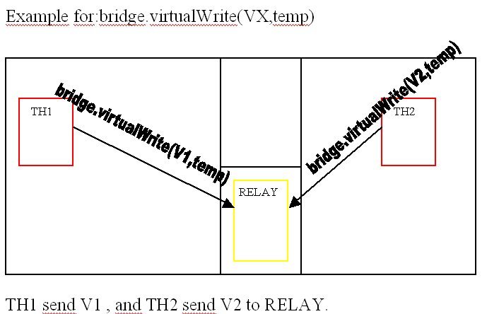
’2. Send the data to the bridged device

I used the following syntax, where the pin used is a Value Display that appears in each of the 2nd and 3rd devices:

bridge2.virtualWrite(V30, value);
bridge3.virtualWrite(V30, value);

whereas you used:

  bridge2.virtualWrite(V1, value);               
  bridge3.virtualWrite(V1, value);

I notice from scanning your QR code that V1 appears 3 times in the project layout and you are using the multiple devices facility. So the 3 V1’s that appear are for device 1, device 2 and device 3.

As I said we ended up with the device selector rather than using multiple devices but the features are closely linked.

So I suspect with the V30 and V1 we are doing the same thing i.e. sending the data to a pin (value display widget) that exists on devices 2 and 3.

Summary

Having written this out I suspect the syntax differences between you and I is the actual bridge definitions. As I used V31 for device 2 and 3 it looks like the library ignores the first definition as it is repeated straight after in the sketch, albeit to a different device, and that is why only 1 device was receiving the bridged data. When I have time I will play around with the definitions to be sure of the correct syntax.

Meanwhile @Dmitriy if you have a minute could you please confirm that for 3 way bridging the syntax for the bridge definitions should be:

WidgetBridge bridge2(V_random_unused_pinX);        
WidgetBridge bridge3(V_random_unused_pinY);

and not simply:

WidgetBridge bridge2(V_random_unused_pinX);        
WidgetBridge bridge3(V_random_unused_pinX);

And that V_random_unused_pin? is a pin in the device doing the bridging rather than any of the devices receiving the bridged data.

@Costas,
you are more than welcome, it’s a pleasure do just the opposite way, help you (a bit) instead of asking you for help :slight_smile:

The idea was just like you have described, use several bridgets to link all the devices, so:

V4 used with Device 1 to be updated from Device 2 and Device 3
V5 used with Device 2 to be updated from Device 1 and Device 3
V6 used with Device 3 to be updated from Device 1 and Device 2

Local server 0.21.7? New release? I only can see the 0.21.6 at GitHub at the moment.

Kind regards!!

Sorry, no it is 0.21.6, it was the app version that just changed from 2.6.0 to 2.7.0.
So many version numbers :slight_smile:

@psoro I have your 3 sketches running on 3 WeMos’ and it looks to be fine.

I have changed the sliders to Send on release, ON, and made them full width size. I have also shuffled the position of the 6 Value Displays so the 2 for device 1 are next to device 1 slider, the 2 for device 2 are next to device 2 slider etc. This way you can better visualise what is happening on the other 2 devices when you change the slider on the 3rd device.

I will play around with the coding when I have time just so I am sure my assumptions on the syntax are correct.

2 Likes

Hello,

i have similar problem.
I have two thermostat at two floor.
I like control two relays in my energy room.
This examples working.

But im thinking…
Is possible read virtual value? Like as virtualWRITE… but i need virtualREAD !!!
For me is better solution.

BRGreg

@GsmKey I think syncAll and syncVirtual are what you are looking for in respect of “virtualREAD”.

Not sure if that’s the best solution for you without knowing more details of your project but it’s certainly worth you checking the docs for syncVirtual.

We are talking about BRIDGE.
For example:
bridge1.virtualWrite(V1,1);
This part is ok. But i need
bridge1.virtualRead(V2);
I need this procedure or. similar?

BR
Greg

@GsmKey please expand upon your “2 thermostats, 2 floors, 2 relays” so I can understand your concept of virtualRead. I could guess what you want to do and what values you are working with but it’s easier if you provide the specifics.

Is possible to read in RELAY value from TH1 and TH2?

BR Greg

What MCU do you have attached to the relays?

TH1 , TH2 and RELAYS is ESP8266 version 12F (nodemcu).

Tnx
Greg

You never really provided the details of what you are wanting to do.

Presumably the 2 relays are connected to a single nodemcu and they are receiving signals from each of the other two nodemcu’s with the temperature sensors attached.

Are the 2 relays independent of each other i.e. temperature changes in room 1 then turn relay1 on / off and temperature changes in room 2 then turn relay2 on / off?

If this is not the case please explain the function of the relays.

I’m trying to work out why you need this “virtualREAD”

I may be totally off on this, but I will give it a try.

on TH1, bridge1.virtualWrite(V1,temp); //would send a value of temp to virtual pin 1 on bridged device 1 (RELAY).
on TH2, bridge1.virtualWrite(V2,temp); //would send a value of temp to virtual pin 2 on bridged device 1 (RELAY).
on RELAY,
BLYNK_WRITE(V1){
int pinData = param.asInt(); // pinData variable will store value that came via TH1 Bridge
}
BLYNK_WRITE(V2){
int pinData1 = param.asInt(); // pinData1 variable will store value that came via TH2 Bridge
}

you could then use pinData and pinData1 in the RELAY code to do stuff.

WHY need READ.

Id like use one master ESP8266. At this point use function WRITE and READ.
Id like optimizate sample from TORO_BLANKO.

In my plane is complex house regulation.
In center is MASTER. All around are SLAVE.
Master READ data from SLAVE ( temperature) and WRITE ( Light switch) on slave.
Program on SLAVE is EQUAL for ALL.
MASTER control all data in run different scenarius on SLAVE.

BR GREG

I use this system with numerous master units sending 1’s and 0’s to a distant ESP-controlled relay. The relay unit adds up the numbers- if they are >1, the relay turns on and they all add up to 0, it turns off. I have a little bit of logic in there that does a virtual write of 0 to each receiving pin after it does the reading just in case one of the master units dies after sending over the 1 value. The master units send values every 5 seconds or so, and the slave adds up the values every 30 seconds.

1 Like

@GsmKey temperature controlled light switch sounds like a strange project but nonetheless @Toro_Blanco and @zeeko have given you some good tips on how to proceed.

Just a point on @Toro_Blanco’s code extract:

Many examples for BLYNK_WRITE will show the param.asInt() as a local variable but this will need to be a global variable if you are going to combine it with SimpleTimer or your own functions etc.

Come back to us if you have further questions and we would need to know if the light switches are independent of each other for the 2 rooms you refer to, which you would expect them to be.

I may have an example that might need a virtualRead on bridge or maybe Blynk has better method to do the following case.
I have 9 devices of NodeMCU each with an ACS712 current sensor attached. each device monitors a water pump. If the current sensor senses current up to a certain value (threshold), then a LED in Blynk app project will become green. if it is under the threshold, it will be red. this threshold will be uniform for all 9 devices. if i want to change this threshold, i dont want to upload arduino sketch 9 times for each device. i also dont want 9 sliders or step widgets in my blynk app. I want only one Step widget which can set the threshold for those 9 devices. i dont mind adding another device as a MASTER. (which makes the 9 devices SLAVES)

looking forward to any responses

thank you Blynk team and Blynk Community

Have you considered the Device Selector widget for devices / tags? 1 slider / 1 step widget but selectable for each device.