My friend lives alone and spends a lot of time at work. He needs to feed a cat and a dog in his house. He asked me some weeks ago to make something that helps him feeding his pets automatically by setting a timer. Then the story begins.
OVERVIEW
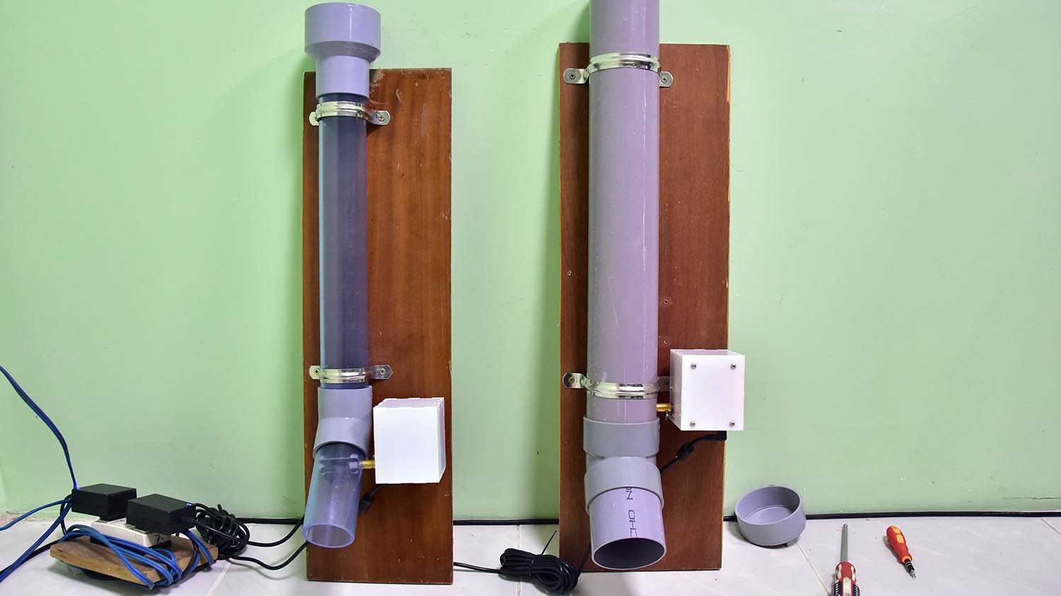
The main food holder is made totally from water pipe. You can choose to use 30 mm, 60 mm, or 90 mm diameter water pipe if you want, so you can feed small one (fish) to large one (dog) and also extend the length of water tube to store more food to feed. I made three designs of fins at the bottom for each size. You can also buy transparent tube to see the amount of food left inside. All the electric & motor parts are put inside a white acrylic box to make it neat and simple. You can directly control the feeder and set up timer to release food by phone from anywhere as long as your phone has the internet connection. There is a public server in between your phone and the feeder. That server saves all the timers you created, then control the feeder to release food at matching time. The feeder needs connection to the internet all of time, otherwise it cannot receive data from the server to operate appropriately.
https://www.youtube.com/embed/jDk9VUJt0jo
The Android app provides the following features:
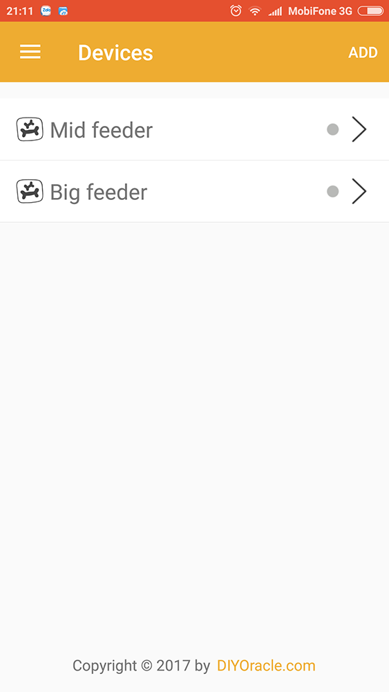
- Add more feeders to control
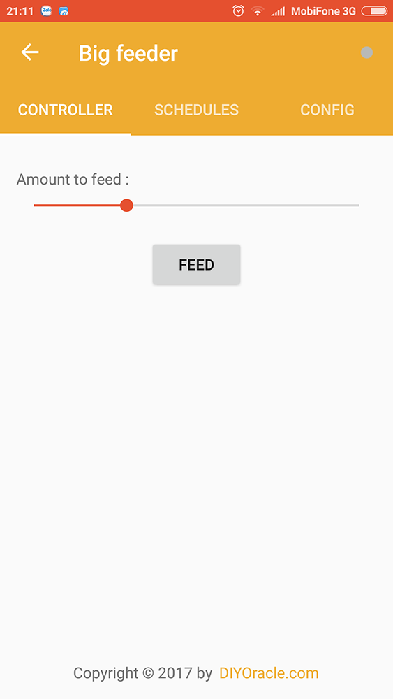
- Push button to feed
- Change the amount to feed
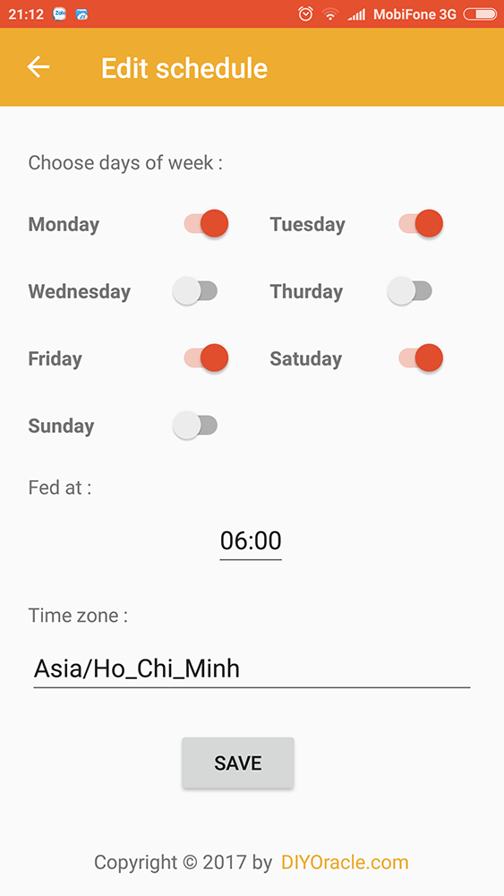
- Set timers to feed (all timers are stored on public server, so do not need to open the app on your phone all time)
- Change timezone to suit anywhere on the world
HARDWARE SECTION
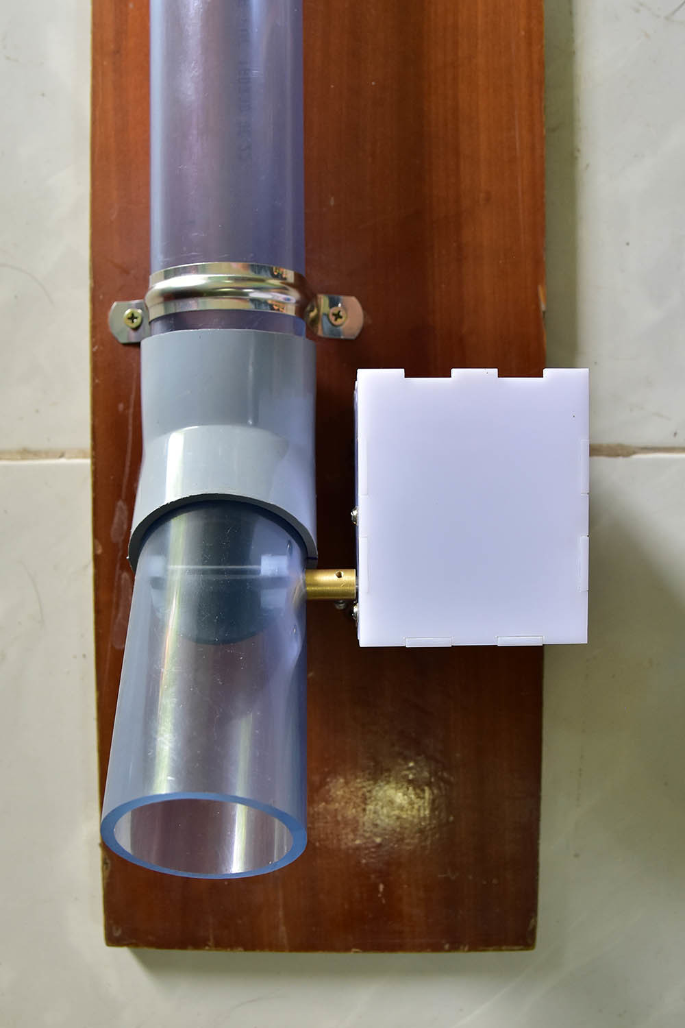
Food holder
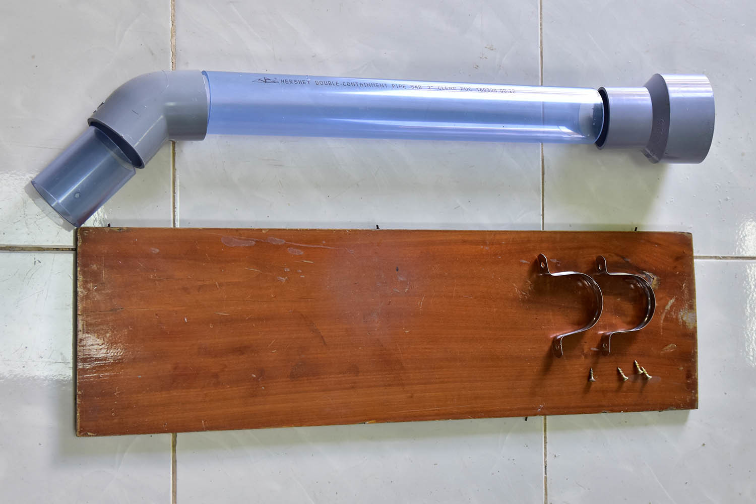
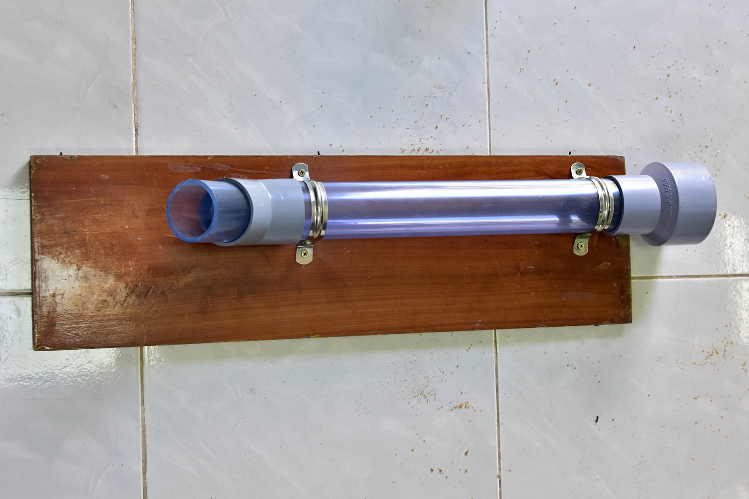
Parts :
- 1 meter water pipe (or whatever length is suitable for you)
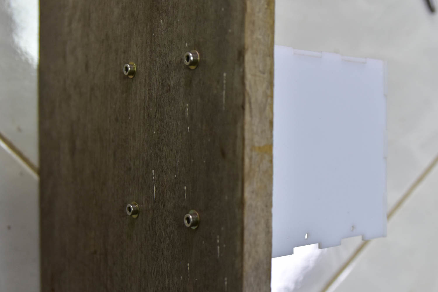
- 2 x aluminum water pipe holder to stick the tube a wooden panel
- 25x80cm wooden panel
- 1 x 45 degree water pipe joiner
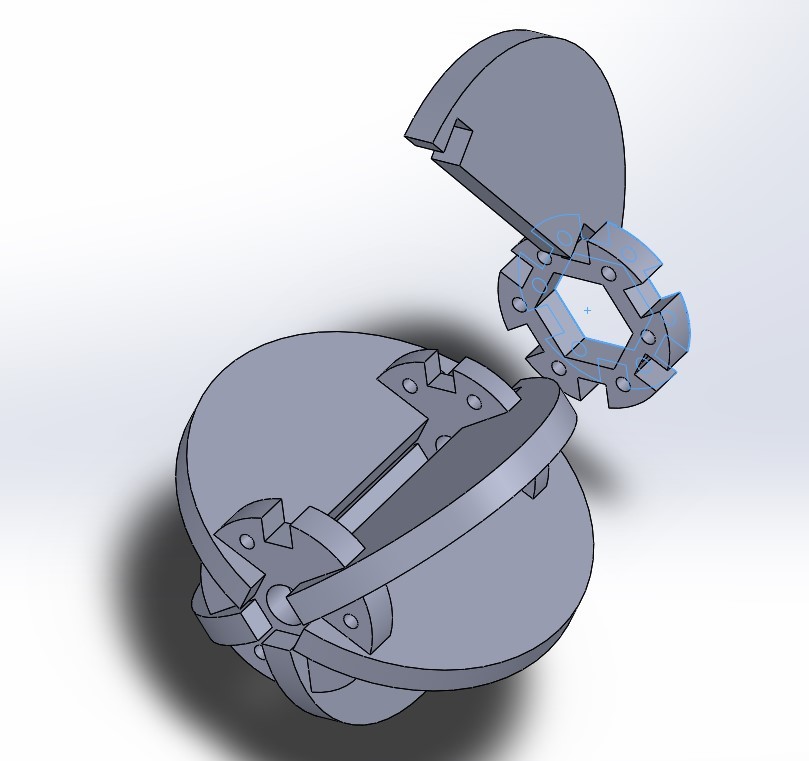
Food dispenser fins
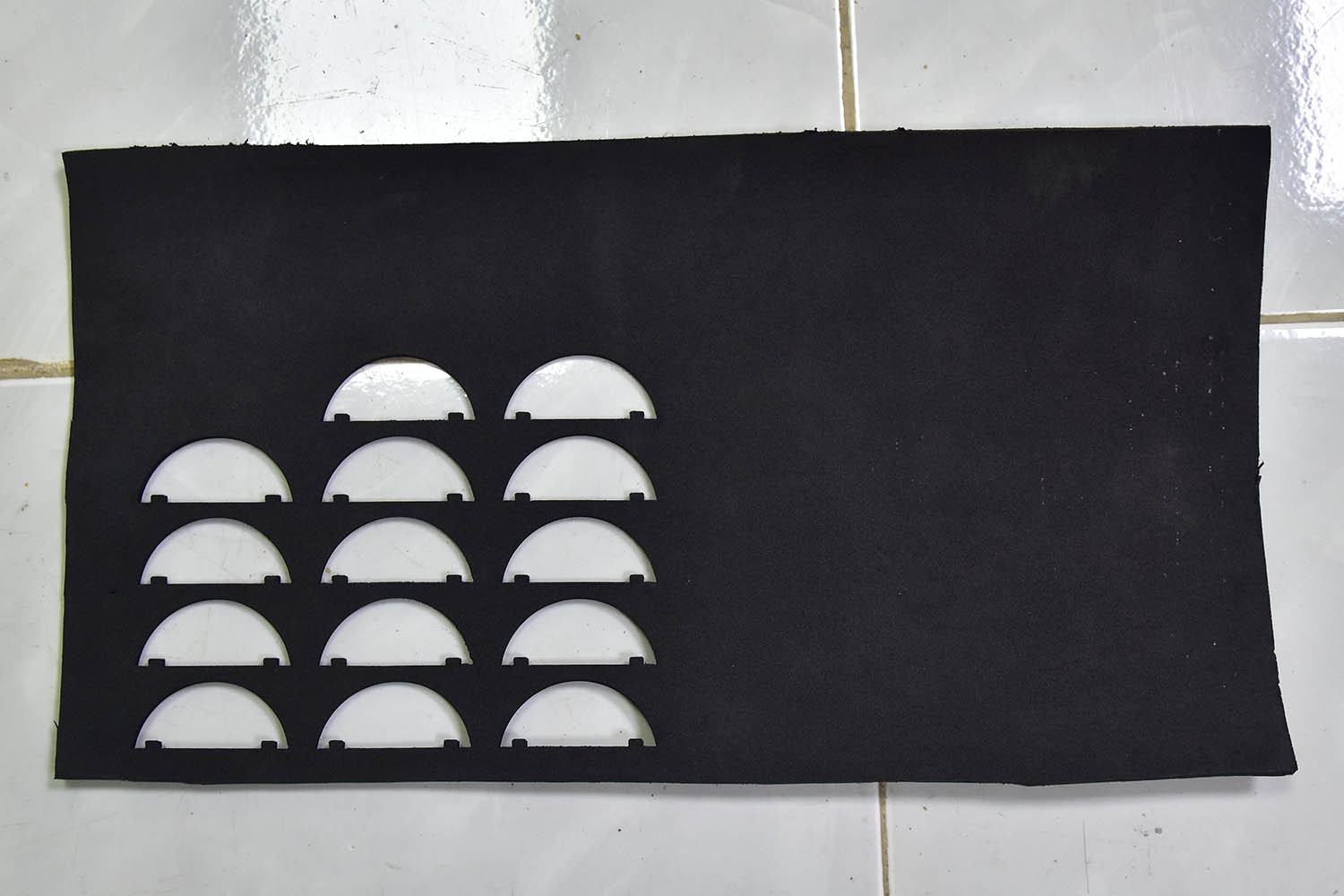
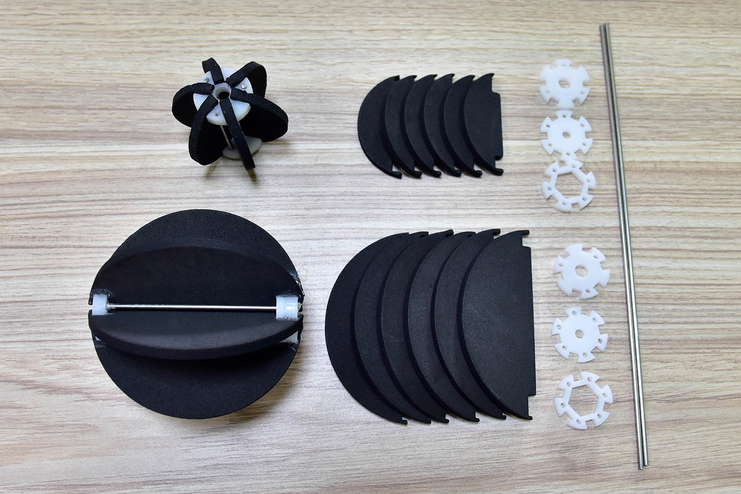
Parts :
- 6 x lazer cut rubber fins
- 1 x lazer cut 5mm acrylic
- 1 x lazer cut 5mm acrylic
- 1 x lazer cut 3mm acrylic
- 1 x 6mm DC Motor Hex Coupling Coupler Copper
- 2mm steel to strengthen the structure
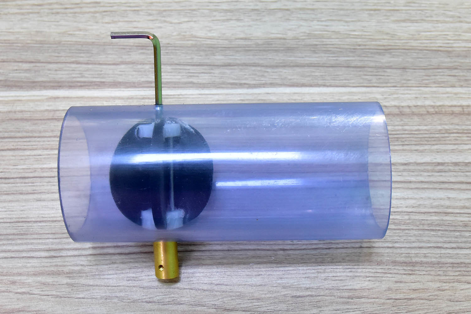
Just using glue to put all parts together as in the photo, then put the fins inside the 60mm tube and attach DC Motor Hex Coupling Coupler on the correct side, use hexagon lock to tighten the screw on the other side. Everything is done like in the following picture:
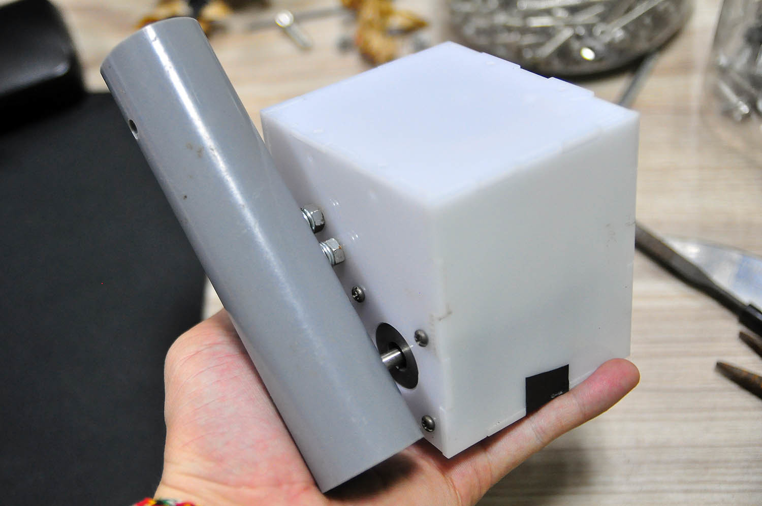
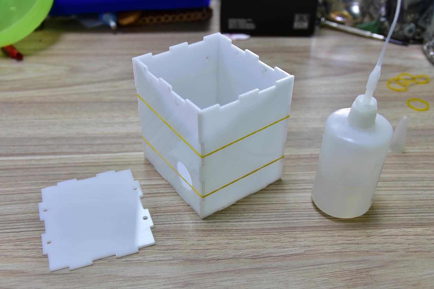
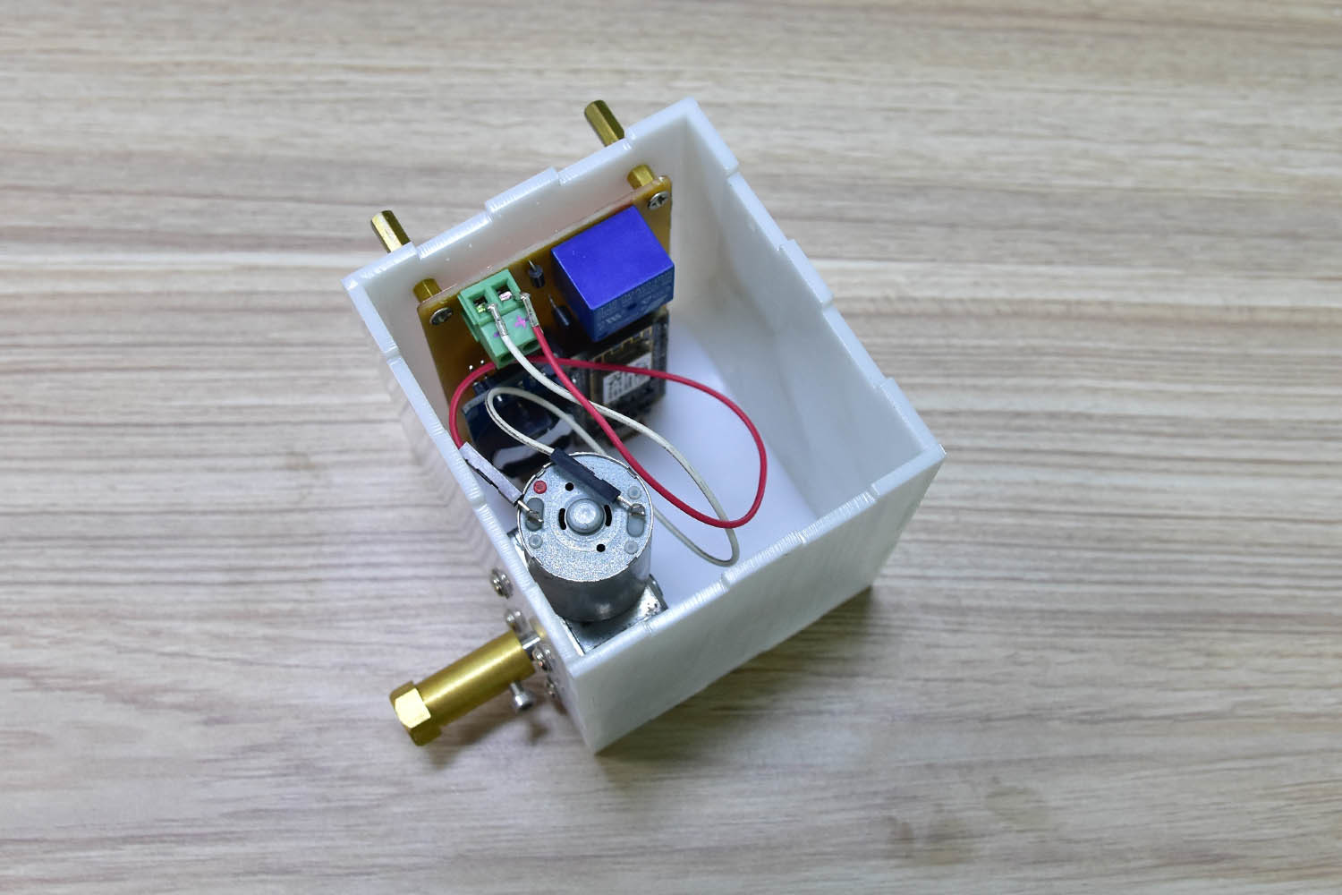
Electric box
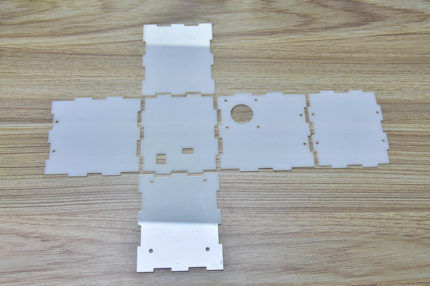
Parts :
6 x lazer cut 3mm acrylic to make 6 faces of the box
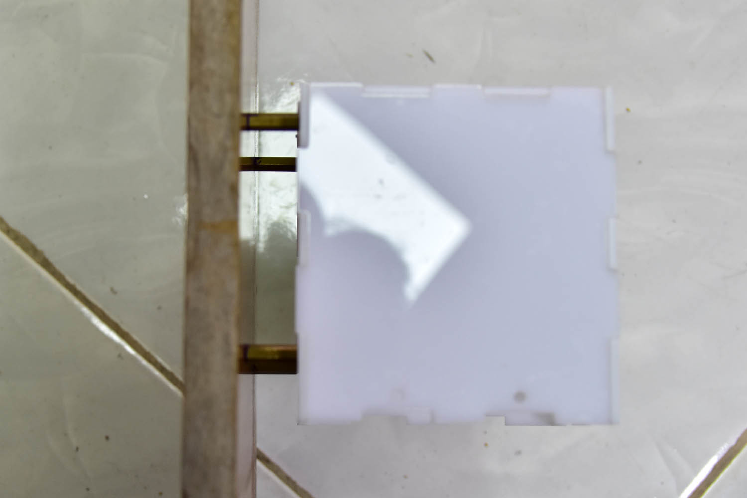
Use glue again to make the box calculate to make accurate hole on the wooden panel use bolt to fix the box to it
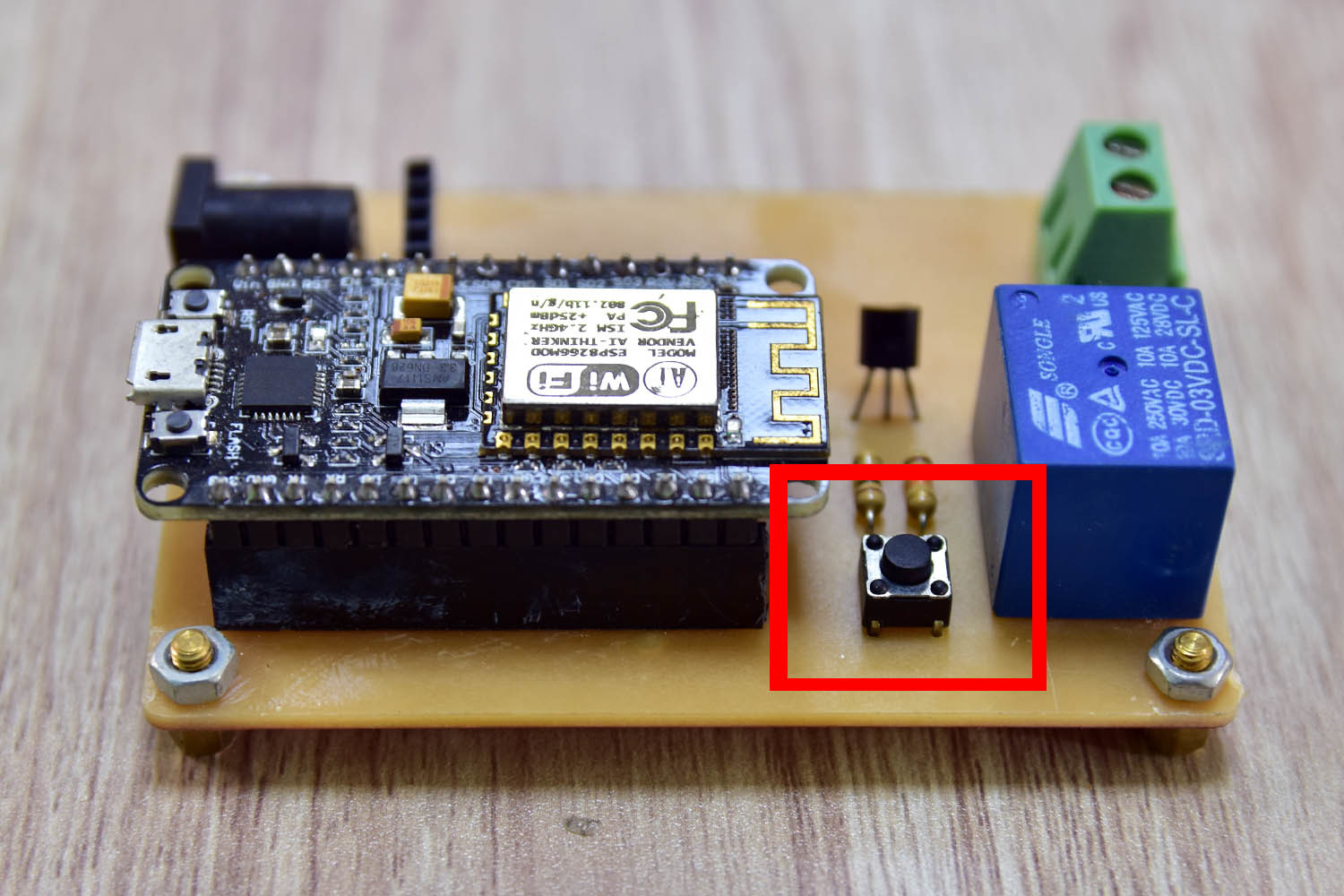
Electric component
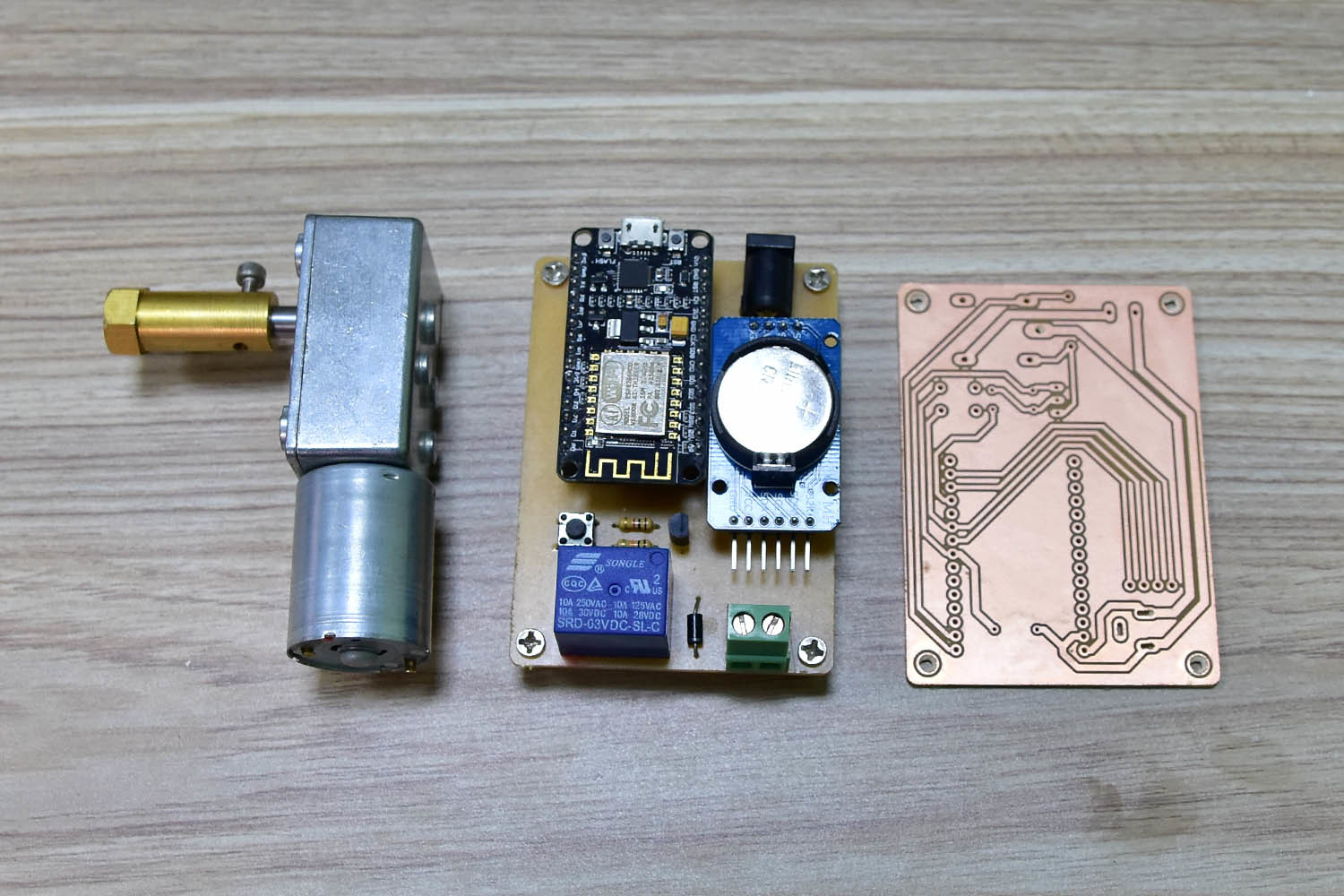
There is a real time module in the photo, but you don’t need it in this version.
Parts:
- 1 x connecting board (feeder.brd - you can download it from attachments section)
- 1 x 12v DC motor with gear box ( 45 rpm )
- 1 x NodeMCU
- 1 x 3.3v Relay
- 1 x 1k resistor
- 1 x 10k resistor
- 1 x transitor 2N3904
- 1 x 1N4007
- 1 x tact switch
- 1 x 2 pole screw terminal block
- 1 x DC power PCB mount socket
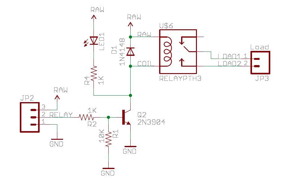
How it Works
DC motor is started and stopped by a relay, The amount of food depends on how long the motor will run. It is fixed from 1 to 8 seconds. I use the following relay schematic to turn on and off the DC motor. Because the voltage of digital pin of NodeMCU is 3.3v so I use 3.3v relay instead of 5v one.
Once you get them all together, you are almost complete with the hardware job.
Firmware
Please download the following programs and files:
- ESP8266Flasher.exe
- feeder.ino.bin
You always need to clear everything in the NodeMCU memory first before a fresh installation. To select the right COM port, look at your Device Manager in your computer after plugging in the NodeMCU board.
The parameters that we are using are as in the following pictures:
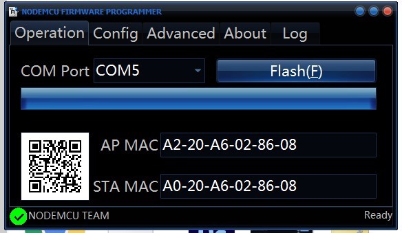
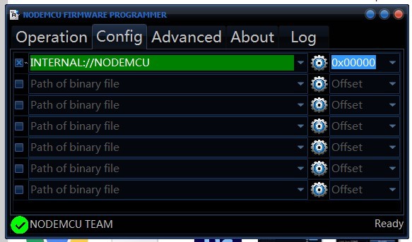
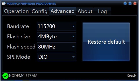
Click the flash button in the Operation tab and wait for flashing to be done.
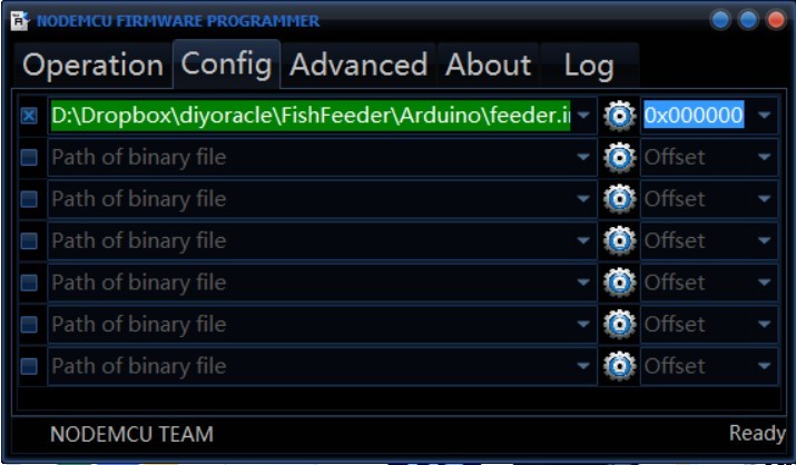
You are now ready to flash the firmware. Go to Config tab again and browse for feeder.ino.bin (Go to Download section to download). Then click Flash button in Operation tab and have a little break.
When everything is done, put the NodeMCU back in your board and you can connect the power source.
How to use the Android app & configure the feeder first time
It is important to plug NodeMCU onto the center board before following these steps, there is a pin connect to the tact switch to clear all the NodeMCU memory if get HIGH. By default, that pin always gets HIGH if not connect to the circuit, and your credentials will be formatted right after they get saved and NodeMCU resets.
https://www.youtube.com/embed/1rsqeXtpdKw
Steps :
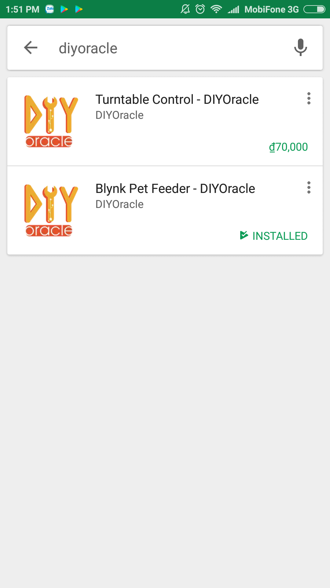
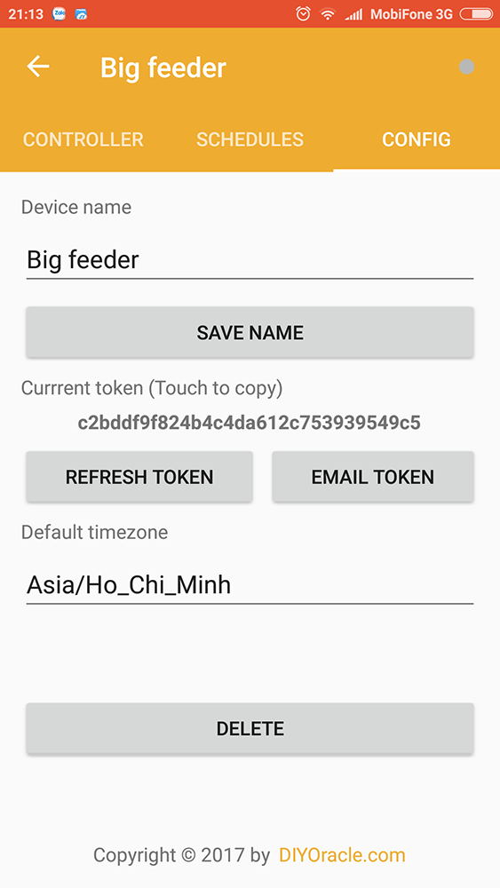
First, you need to install the Blynk Pet Feeder - DIYOracle (free) from Google Play Store, just type “diyoracle” in the searching textbox then you will see it. Register a new account if you don’t have one. Login with your account and you will see a default feeder displayed in the list. Choose it and go to CONFIG tab, touch the token string to copy.
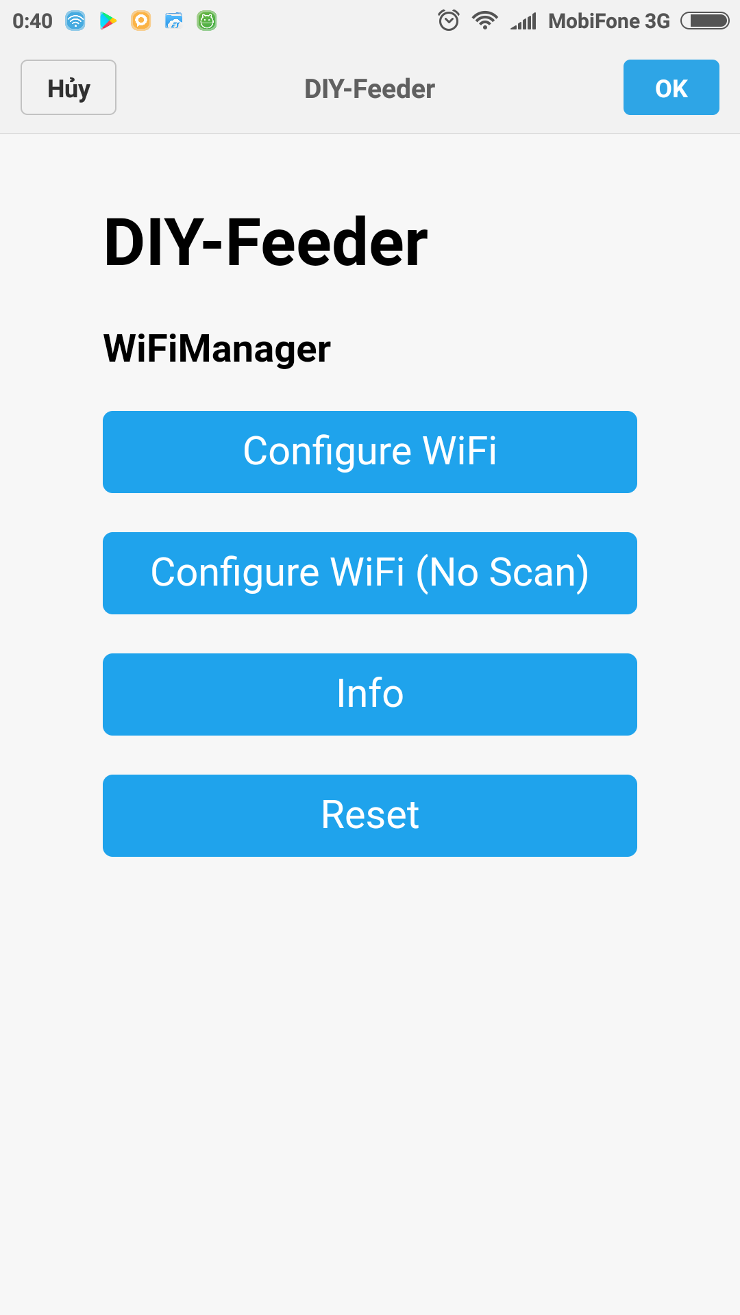
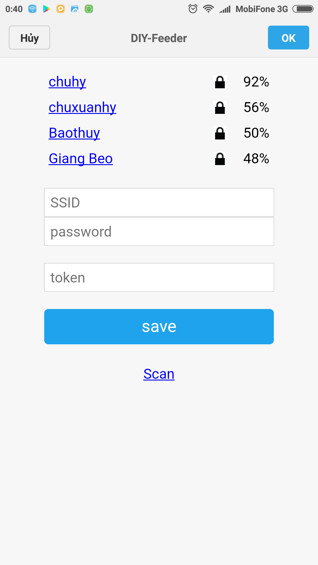
Second, power on the feeder and look for xxxxxx_Feeder displayed in wifi hotspot list and connect. Type 192.168.4.1 in address bar of any web browser to open the configuration portal. Choose Configure WiFi in the menu, type in your wifi uid, pass and finally paste the copied token. Click Save to finish saving them into the NodeMCU memory.
In case the wifi credentials is changed later, you need to push the button on the board to clear all saved data and do configuration step as described again. Remember pushing the button while the power is on.
Third, connect the phone back to the Internet. The feeder is now ready to be controlled by the app. The icon status on the right should go green to indicate that the connection with the feeder has been made successfully. Try to change the amount and click Feed button to test the operation. All timers are set in the SCHEDULES tab, remember to change the timezone to suite your location otherwise it will not run on time.
Finally
You can add more feeders if you want, there is an ADD button on top of the right in the list screen. Each feeder need to provide a unique token to work properly.
Link to download all files : http://diyoracle.com/wp-content/uploads/2017/07/FoodDispenserElectricbox.zip