Yes but you had been Blynking quite some time when you got your ESP so you had covered some of the 50 steps.
Actually I think it took me about a week with my ESP-01’s and I’m confident there is a big group of people that gave up on them, and Blynk. I had about 50 Nano’s at the time and thought these ESP’s (01’s) would be a great addition.How wrong I was when I realised the dev boards cut out so much effort.
What happens for many people, me included, is they get the ESP-01 and flash a standalone sketch and they wonder why it doesn’t work. Included in the 50 steps are realising you need the AT firmware.
Where is the AT firmware, which version, how do I flash it? Do I need caps, can I power from Arduino. Voltage regulator. Which library, which IDE, baud rates, TX to TX or not? It goes on and on (50 steps in total).
I now have around 50 ESP’s in total and would much rather use one of the dev boards as a shield than an 01. OK so I’m a software guy more than a hardware guy but either way 01’s should only be used if you are very, very short of funds or have a tiny footprint for your project.
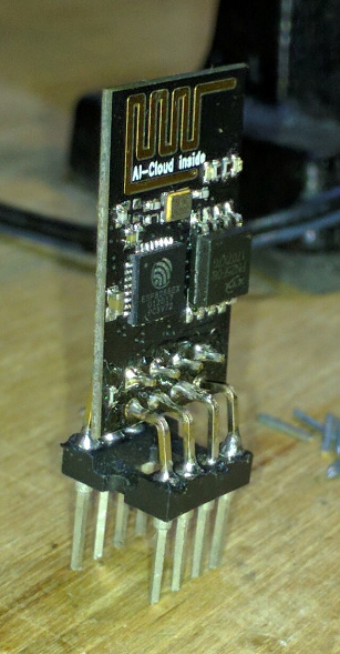
The most annoying thing about the ESP-01 is mainly its not breadboard friendly !! and the second thing is it does not have an on board voltage regulator. And what ever we do it should be under 3.3v… Which is actually at times annoying. Even the Rx and Tx lines are 3.3v and needs voltage divider and other supporting components to get that little piece getting to work without destroying it… But where as our Nodemcu takes any beating that we give. And most of all its breadboard friendly. Hooking up things and testing is damm easy !!
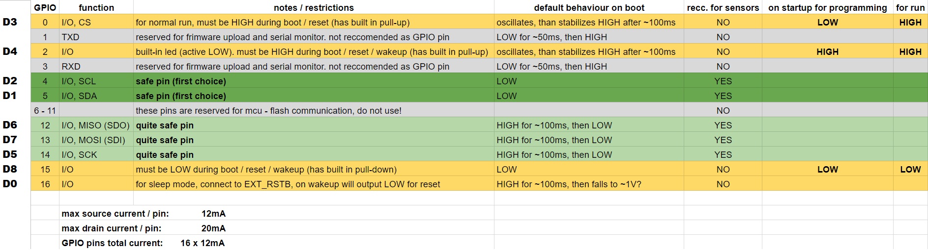
No need of Gpio’s being pulled low or high during updating the firmware…
This is the only reason i refuse using that tiny little piece !! Even though we spend a couple of $ extra … It saves our time and is hassel free…
Only the RX really matters for that… and even then, my RC car is still working fine with a 5v incoming TX signal. Granted, being a signal and not a power sink it is not a constant voltage, so able to handle it to date.
Generally that only needs to be done once ever for AT firmware. And even with my Blynk sketch version, after the initial, I use OTA from then on for flashing.
Yep… that’s me
Actually, I think I it is a combo of the ESP-01 being my initial foray into ESP world. It worked without hassle. And I enjoyed succeeding in something that I heard was a challenge.
Had I had more bad experiences, then I might be more jaded… but thankfully I am not.
But again its an hassel to give time and solder the header pins.
But for some reason I don’t find that seem to be professional thing. It doesn’t have that attire of that professionalism and i have never found on a commercial product … it feels too tiny though.
And actually nodemcu sits on my breadboard and give me a row of free holes to hookup the jumpers… and if we need to extend that in many ways.
I am more a techno geek with steampunk attributes, so while I can certainly appreciate Star Trek cleanliness… I also like to see the roots of the wires
What are you making again anyhow with your ESPified UNO?
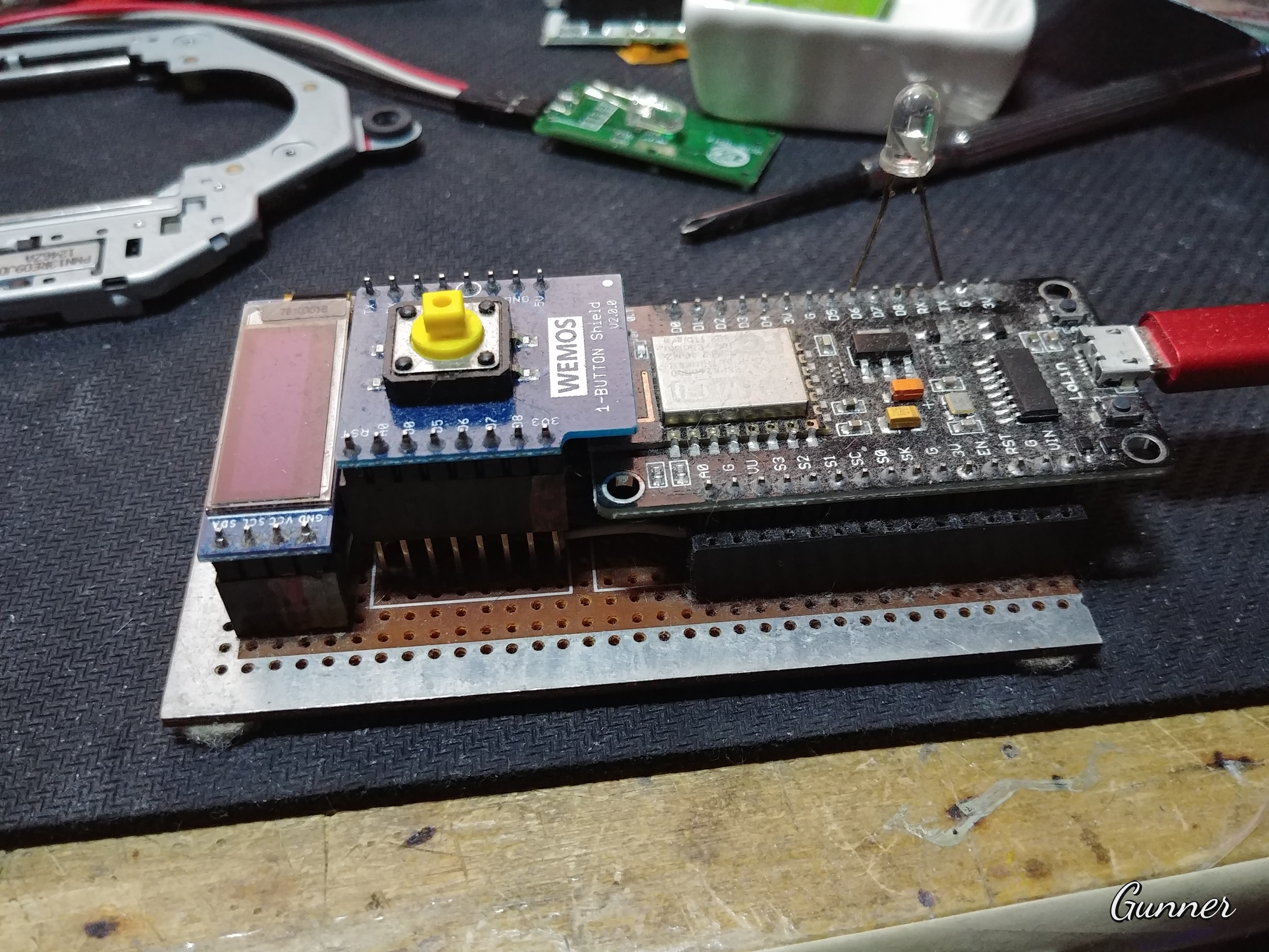
Actually i was using the nodemcu alone. But when the power recycles the pin goes high and it in turn made the relays go high… Turning on the devices connected to it, and later sync with the local serveBut now i guess by using this setup. The problem will be solved…
What do you think ? Is a better way or a much simpler way to achieve this ?
Depends on what pins… But yes a first-thing-sync can quickly resolve that, and I seem to recall someone saying using capacitors may give the needed millisecond buffer in case the relays still try to pulse.
So you’re saying that we went though all of the “50 steps to enlightenment” just to solve a problem with relays going high at start-up?
I wish you’d have explained that earlier, there are some simple solutions to that problem when using the NodeMCU as a standalone device.
Tried all sought of stuff to buffer the pulse during the startup !! I used some huge capacitors to soak in the initial pulse. But it some how made through the capacitor and triggered the relay. Actually the relays transistor’s need a very low current and voltage to trigger the relay. And the charge left behind by the capacitor is enough to trigger the relay. Now i feel i need to put in a mosfet that drives on high voltage (ex.12v) and this this will in turn control the transistor !!
Hmmm now am starting to get some idea…But am not sure this will work or not. Gotta try that out…
We are talking only milliseconds before code can rectify the situation. Smaller capacitor with drain resistor… something that can’t keep up with a solid HIGH signal, and thus disrupt it, but still able to drag a small pulse down to GND.
Or now that I type this, perhaps just some additional external pull up/down resistors, depending on preferred default mode of a pin?
Why your thinking is so narrow ? Relays going high on boot is not the only problem. There are certain libraries and code that does not work with the ESP architecture ! And in that cases one can use this method. Instead of changing the whole code giving days of time just to fix the code for ESP. So this will ease the process a bit.
Can you please tell us what was the simple solution you follow, so even we can try that out !!
I will explain the scene,
The relay module is active low. And when the power cycles and the nodemcu reboots and till it takes time to get in sync with the local server it will stay high.
And incase the the local server was also rebooted then the server will take some where around 50sec to 1min… Till then the nodemcu will wait for the server link and keep the relays high.