Hi Blynkers,
I wanted to show a small set-up using the ADS1115 with the Wemos Mini D1. This is not a “project” by itself, I posted several photos and more details in the forum a few months ago but the info was a little bit disordered so I think it’s a good idea to post all info together… I guess it could be useful in order to spread the world about Blynk  …
…
-Description:
The ADS1115 is a 16 bit Analog Digital Converter:
-Library required:
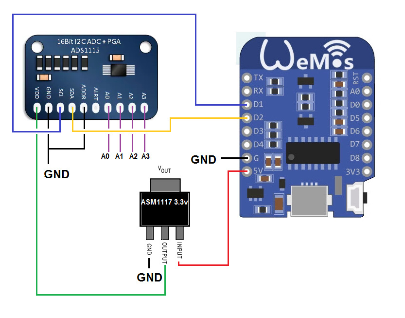
-Schematics:
-The code (Keep in mind I’m a Local Server guy, update the code accordingly…)
#include <ESP8266WiFi.h>
#include <BlynkSimpleEsp8266.h>
#include <SimpleTimer.h> //Blynk
#include <Wire.h>
#include <Adafruit_ADS1015.h>

#define server "xxx.xxx.xxx.xxx"

char auth[] = "***************";
char ssid[] = "***************";
char pass[] = "**************";

bool isFirstConnect = true;
SimpleTimer timer;


 Adafruit_ADS1115 ads;  /* Use this for the 16-bit version */
//Adafruit_ADS1015 ads;     /* Use thi for the 12-bit version */
float Voltage0 = 0.0;
float Voltage1 = 0.0;
float Voltage2 = 0.0;
float Voltage3 = 0.0;

void setup()
{
  Serial.begin(115200);
  Blynk.begin(auth, ssid, pass, server);
  int mytimeout = millis() / 1000;
  while (Blynk.connect() == false) { // try to connect to server for 10 seconds
    if((millis() / 1000) > mytimeout + 8){ // try local server if not connected within 9 seconds
       break;
    }
  }
  timer.setInterval(350L, ReadANAlOGS);
  timer.setInterval(30000L, reconnectBlynk);  // check every 30s if still connected to server


  // The ADC input range (or gain) can be changed via the following
  // functions, but be careful never to exceed VDD +0.3V max, or to
  // exceed the upper and lower limits if you adjust the input range!
  // Setting these values incorrectly may destroy your ADC!
  //                                                                ADS1015  ADS1115
  //                                                                -------  -------
  // ads.setGain(GAIN_TWOTHIRDS);  // 2/3x gain +/- 6.144V  1 bit = 3mV      0.1875mV (default)
  ads.setGain(GAIN_ONE);           // 1x gain   +/- 4.096V  1 bit = 2mV      0.125mV
  // ads.setGain(GAIN_TWO);        // 2x gain   +/- 2.048V  1 bit = 1mV      0.0625mV
  // ads.setGain(GAIN_FOUR);       // 4x gain   +/- 1.024V  1 bit = 0.5mV    0.03125mV
  // ads.setGain(GAIN_EIGHT);      // 8x gain   +/- 0.512V  1 bit = 0.25mV   0.015625mV
  // ads.setGain(GAIN_SIXTEEN);    // 16x gain  +/- 0.256V  1 bit = 0.125mV  0.0078125mV

  ads.begin();
}

BLYNK_CONNECTED() {
if (isFirstConnect) {
 Blynk.syncAll();
 Blynk.notify("ADS1115 STARTING!!!!");
isFirstConnect = false;
}
}

void ReadANAlOGS()
{

  int16_t adc0, adc1, adc2, adc3;

  adc0 = ads.readADC_SingleEnded(0);
  adc1 = ads.readADC_SingleEnded(1);
  adc2 = ads.readADC_SingleEnded(2);
  adc3 = ads.readADC_SingleEnded(3);

  Voltage0 = (adc0 * 0.125)/1000;
  Voltage1 = (adc1 * 0.125)/1000;
  Voltage2 = (adc2 * 0.125)/1000;
  Voltage3 = (adc3 * 0.125)/1000;

 //Serial.print("AIN0: "); Serial.println(Voltage0);
 //Serial.print("AIN1: "); Serial.println(Voltage1);
 // Serial.print("AIN2: "); Serial.println(Voltage2);
 // Serial.print("AIN3: "); Serial.println(Voltage3);
 // Serial.println(" ");


  Blynk.virtualWrite(V0, Voltage0);
  Blynk.virtualWrite(V1, Voltage1);
  Blynk.virtualWrite(V2, Voltage2);
  Blynk.virtualWrite(V3, Voltage3);
}

void reconnectBlynk() {
  if (!Blynk.connected()) {
    if(Blynk.connect()) {
     BLYNK_LOG("Reconnected");
    } else {
      BLYNK_LOG("Not reconnected");
    }
  }
}

void loop()
{

  if (Blynk.connected()) {
    Blynk.run();
  }
  timer.run();
}
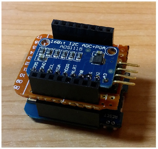
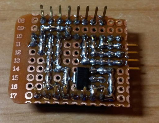
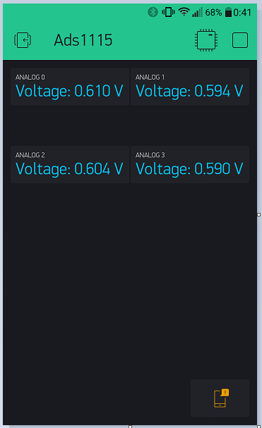
-Some Pictures:

-Video:
-QR:

I hope you like it!
Regards


