On the Arduino, the solution is to issue the digitalWrite(n,LOW) instruction BEFORE you define the pin as an Output with the pinMode instruction.
Have you tried this on your NodeMCU?
Pete.
On the Arduino, the solution is to issue the digitalWrite(n,LOW) instruction BEFORE you define the pin as an Output with the pinMode instruction.
Have you tried this on your NodeMCU?
Pete.
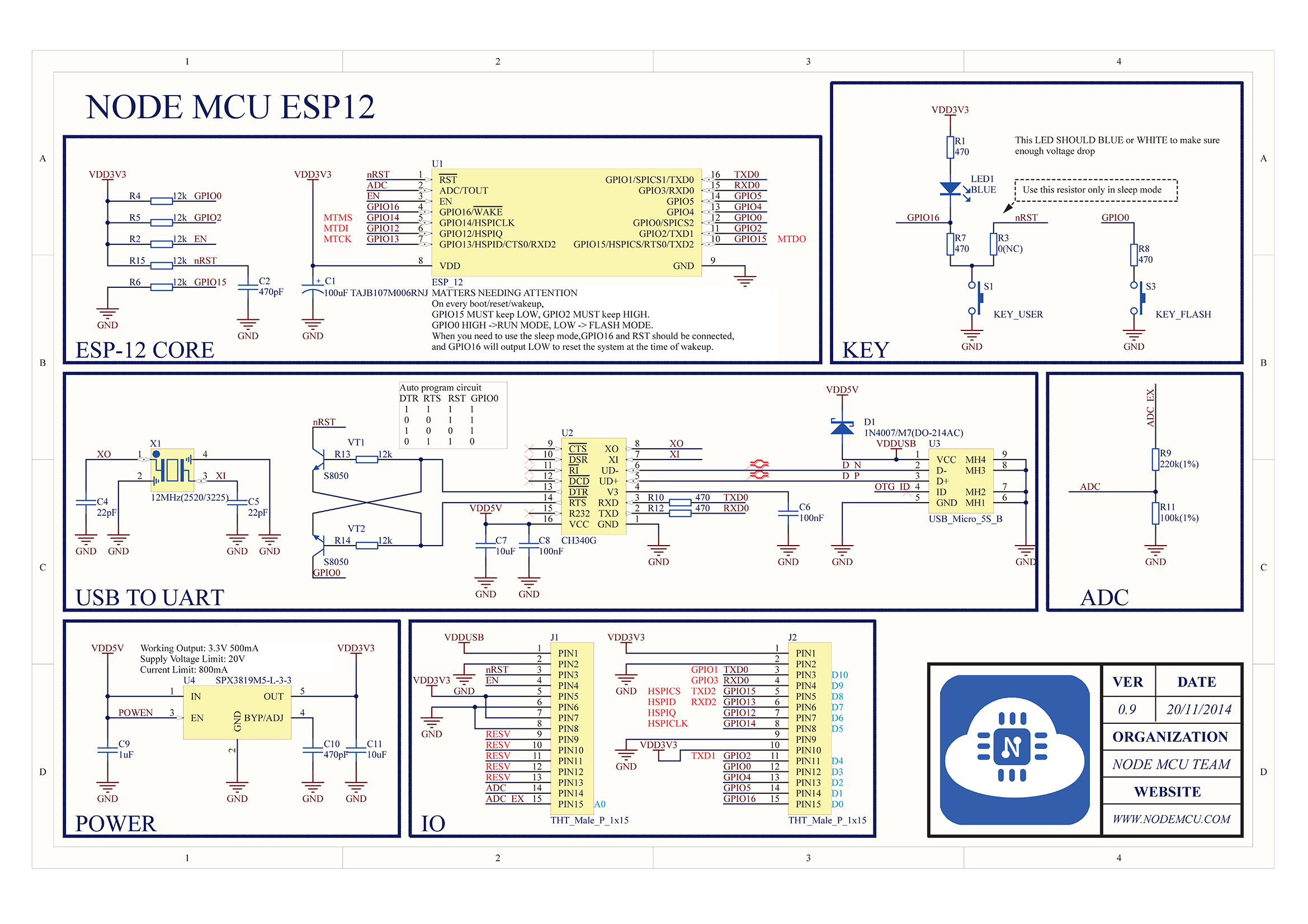
With NodeMCU the problem is, that I/O lines are hardware wired with pullups/pulldowns. Look at default NodeMCU 0.9 schematics:
IF I/O lines are floating after startup (I do not know how it goes in details), then resistors are working the way they are wired (to GND or VCC)
I had this problem. I deleted the button and reinstalled it and the problem was gone.
However (don’t we hate that word), my project is a 2 door garage door opener. Yesterday
I noticed that one of my OPEN LEDs was not working. I reset my Wemos D1 and nothing
worked. I checked and the entire sketch was gone. I reloaded it and it worked then I unplugged
the USB from the laptop and plugged it back into the power supply and nothing. Sketch was gone
tried another board and got the same results. Finally determined that it was the OPEN LED pins.
I think that I need to add Pullup resistors. I removed them from the circuit and the sketch stayed and worked. However (here we go again), now the Right door comes up on power up. I deleted the button and reinstalled it. Right door didn’t come up on power up…however (), the left one did. Deleted and reinstalled it, left works and theright comes up on power up. Deleted both and reinstalled both and the left comes up on power up. I walked away before I inflicted severe damage to the circuit!
I think the problem is with Blynk some how. Before I installed a DHT22 in the equation the Delete/Reinstall worked and the problem did not jump to the other button.
i have the same problem with nodemcu. the gpio 0,1,2,3 are high when bootup. when i attach a switch with pull down resistance, the board will boot when the switch is on. but if the switch is off and i restart the board the board will not bootup. need help… please… thank you…
Same here. I have 2 reed switches (NC) that pull a GND to the IO pin. If the power goes out
the device will not go back online. If I manually open both garage doors and reset the unit, the
device will go online. I am at a loss.
Maybe this is the reason.
https://zoetrope.io/tech-blog/esp8266-bootloader-modes-and-gpio-state-startup/
Yes, this is the reason. Certain pins must be low in order for the nodeMCU 1.0 to boot properly, Pin 0 (marked as D3 on the board) is always high on startup.
Then you simply set the pins to the required state in your sketch.
I dont have any issue when using the ESP12F / ESP12S standalone ones so I can say that your case some pins are hardware pulled up (or default schematic of the NodeMCU board) or the High stage may come from the hardware connecting to your NodeMCU.
As long as you find out the default stages of your NodeMCU board then you will know how to develop / revise your codes or you could use some isolating components to get what you want. Most of relays are low trigger that is why the output of ESP based board should be HIGH right after booting up.
That was it Toro! I stopped using pins D3, D4 and D8 and it works great.
Thanks
I know it’s late on this thread but I believe what you need is a pull-down resistor on that pin. I had the same issue and connected the pin to ground with a 4.7K resistor. I am new to this so not sure what the optimal size resistor would be.
pin --> 4K7 --> ground
This would be inline with whatever else you are connecting that pin to.
@myrddin Not so fast with that solution  There are sometimes special purposes for ESP pins that are activated by grounding them during bootup… i.e.
D3 - GPIO0, when grounded, puts the ESP info FLASH mode.
D4 - GPIO2 is TX1 or part of the serial (USB) communication, and having it grounded (or HIGH) during programming might interfere with that ability.
Ah yes, forgot about that. Thank you. Also I was using esp8266 as part of a NodeMCU and it was GPIO pin 4 (D2). I had D2 connected to ground via 4k7 resistor and also to a physical button to send HIGH when button pressed and LOW when button not pressed. Only way I could get it to work was by pulling that pin down. Otherwise it always stayed HIGH.
Hi All. I manage to remove the issue by removing all traces of blynk from my sketch. None of the pins are now activating the relays on start or reboot. So it must be something to do with the blynk library.
I will have to look further into this. But definitely something to do with the incorporation on blynk.
Thanks
If you’re using direct pin manipulation via the Blynk app (rather than using virtual pins) then the pins going low on boot-up of your MCU is intentional behaviour of the Blynk library. It’s discussed in detail in this thread:
If that behaviour isn’t acceptable then the simple workaround is to use virtual pins (which is the most sensible approach anyway).
Pete.