You just need a shared ground when using multiple power sources.
Plug that thing into the breadboard and feed the 5v power and ground rail to the relay, but also jumper a ground wire from the ground rail to a ground pin on the board
You just need a shared ground when using multiple power sources.
Plug that thing into the breadboard and feed the 5v power and ground rail to the relay, but also jumper a ground wire from the ground rail to a ground pin on the board
You guys are amazing. Its working and clicking.
I will do the research into what i need in order to combine the relay to turn on and off an ac light.
Is there anyway to make the nodemcu board work with the relay without the extra power supply.
Just trying to figure out the best to do it with the less parts possibles for easier replication.
Funny, I have never made a tutorial before, but i am exited to do one for this.
Glad it is finally working 
The power board can provide two different voltages, one per each side rails. Jumper the relay side to 5v (I see you have it on 3.3, but the coils will be more reliable on 5v). and set the other rail to 3.3v and power your nodemcu from that rail… I believe you can just plug into any 3.3 pin on the board (make sure to remove the USB first I think?).
Also, if doing that then you can remove that extra ground jumper I mentioned, as that power board already joins the two ground rails together.
Next… grab your camera and we can start working on an oil change for your car or perhaps a new roof 
Okay i will try that in a moment. However i did plug in the relay on the other side and it did nothing like before including the power supply to the equation.
I want to have 3 lights with 3 different boards because they wont be too close to each other. However i want this to be on the samw blynk page by using the target option in the app. How should i go about this?
@Gunner I got the car oil part!
You could buy a 3.3v relay board to replace the 5v board that you have. That SHOULD work okay, but bear in mind that the voltage regulator on the NodeMCU board is stepping-down the USB power and you’d be asking it to drive the board and the relay. If you final solution was one where the relay will only normally be energised for a short period of time (such as operating outside lights that will stay on for a couple of minutes then go off) then a 3.3v relay powered directly off the NodeMCU pins would be fine.
Otherwise, I’d suggest using a power supply similar to the one you’re using at present. This could be wired to power the NodeMCU board from 3.3v and then drive either a 3.3v or 5v relay depending on what you prefer. If you were going down this route you wouldn’t need the external USB supply to power the NodeMCU.
I know I mentioned this before, but have you looked at the Sonoff switches? You can buy one from China for less than £5 delivered and they have an Esp8266 and relay built-in and don’t need an external power supply. You have to connect mains Line and Neutral to them, so in UK wiring at least you’d need to locate it near the ceiling rose for the light, but you’d have similar issues picking-up- a supply to power your home-made device.
You have to solder a 5 pin header onto the board, but this is very easy. If you want an external push-button switch (there’s one on the Sonoff device, but if you’re putting it in a ceiling cavity then it wont be accessible) then you run this from two of the pins on the header once you’ve flashed the code onto the Sonoff.
You need a cheap FTDI programmer to flash the code, but once again these are very cheap.
If you do choose to take a look at the Sonoffs then NEVER connect it to the computer and the mains supply at the same time. You will kill the computer, and probably yourself at the same time. On that subject, be very careful what you do next when you start connecting mains power to your existing setup. Check that everything is connected-up correctly before plugging-in to the mains and make sure that there’s no chance of the mains and the low-voltage electronics coming in to contact with each other while you’re messing around with it on the bench.
Pete.
I have seen the sonoff before and they are great! But for me, these projects are more about gaining the knowledge than saving on cost. Once i have learned a good amount then im fine with taking the easier route.
Good work getting it clicking!
Check out my own “sonoff” style device/code if you like… its basically the same thing as you have made but its turning on my front garden and path lighting at night and when the gate (with ESP attached) opens at night.
Bridge can allow multiple devices to share info and be controlled by a single app.
And a little late to the party, but I finally wired up my Pro Micro using your sketch (modded for my setup) and tested my relay on 3.3v (it lit up, but no click), and again on 5v… works perfectly. So yep, 5v for the coil is needed, at least for mine.
And I had fun helping and making mine along the way ![]()
Honestly thank you, this comunnity is great, you guys actually try to help others and it is great. I appreciate all the help!
Looking good! Dont put it away yet, lets follow it through all the way, but in the morning 
I have an ideas and i am wondering if it will work.
For those who have seen an iphone cube charger, who hasn’t seen one lol, i just read the back label and it says the output is 5v 1A so i am wondering, if i open it up and instead of using the usb cable i solder 2 positive and 2 negative leads. One to the board and one to the relay. Would i be able to run the board and the relay this way? Taking the extra power supply out of the equation. The goal is to have this into a nice slick box with as little as possible components inside.
That would work. You could also buy a small DC-DC stepup/stepdown (buck) convertor. They cost a couple bucks and can lower or increase voltage.
I usually have some psu’s which do 12v at 3A or more. They work great with DC-DC convertors like http://www.ebay.com/itm/10-PCS-LM2596-DC-DC-buck-adjustable-step-down-Power-Supply-Converter-module-/221920170517?hash=item33ab791215:g:5zEAAOSw~bFWKKJO these ones 
Not trying to sound stupid but i dont really know what does are or how they work?
I am looking for the best way to power the nodemcu aswell as the relay with the less components as possible.
Btw the best way to connect all this together is by soldering everything in a prototype board or what do you guys recommend?
Basically it converts any given DC into a (lower) other DC voltage.
I use basic 12v power supply’s for all my projects, but usually I need a bit less. So, I add one of those things (there is little variable resistor on there) so I can step down the 12v to 5v or any other voltage I need.
Oh ok i understand now, but in that case i would still need a dc power supply. If i use the phone charger i can just tap into the ac line that is passing through the relay to go to the light.
I will make a diagram tomorrow for better explanation. I want you guys to check it out before putting it all together neatly in a box.
Okay so after getting some rest i went ahead and put everything together to do a live test with the ac light bulb. I am happy to say it works great.
However, something weird happen, i plugged in the relay to the 3.3v pin coming out of the nodemcu board and the relay is now clicking with no extra power supply. Any ideas as of why? And will it be stable if left like this?
That’s a lack of power… prob not good to be drawing so much current from the MCU pin.
3.3v power on a device rated for 5v means that you are providing just over half of what is it expecting, and also due to the variable nature of an electromagnetic field, that relay is just on the verge of sometimes working or not… aka not reliable.
Not to mention the unnecessary load on the MCU’s 3.3v regulator as @Jamin said.
Another reason to make good and solid relay connection is possible chatter if the coil is only just barely doing its job. chatter meens potential sparking on the contacts and with AC that will burn out your relay connections… potential fire hazard.
Okay makes sence.
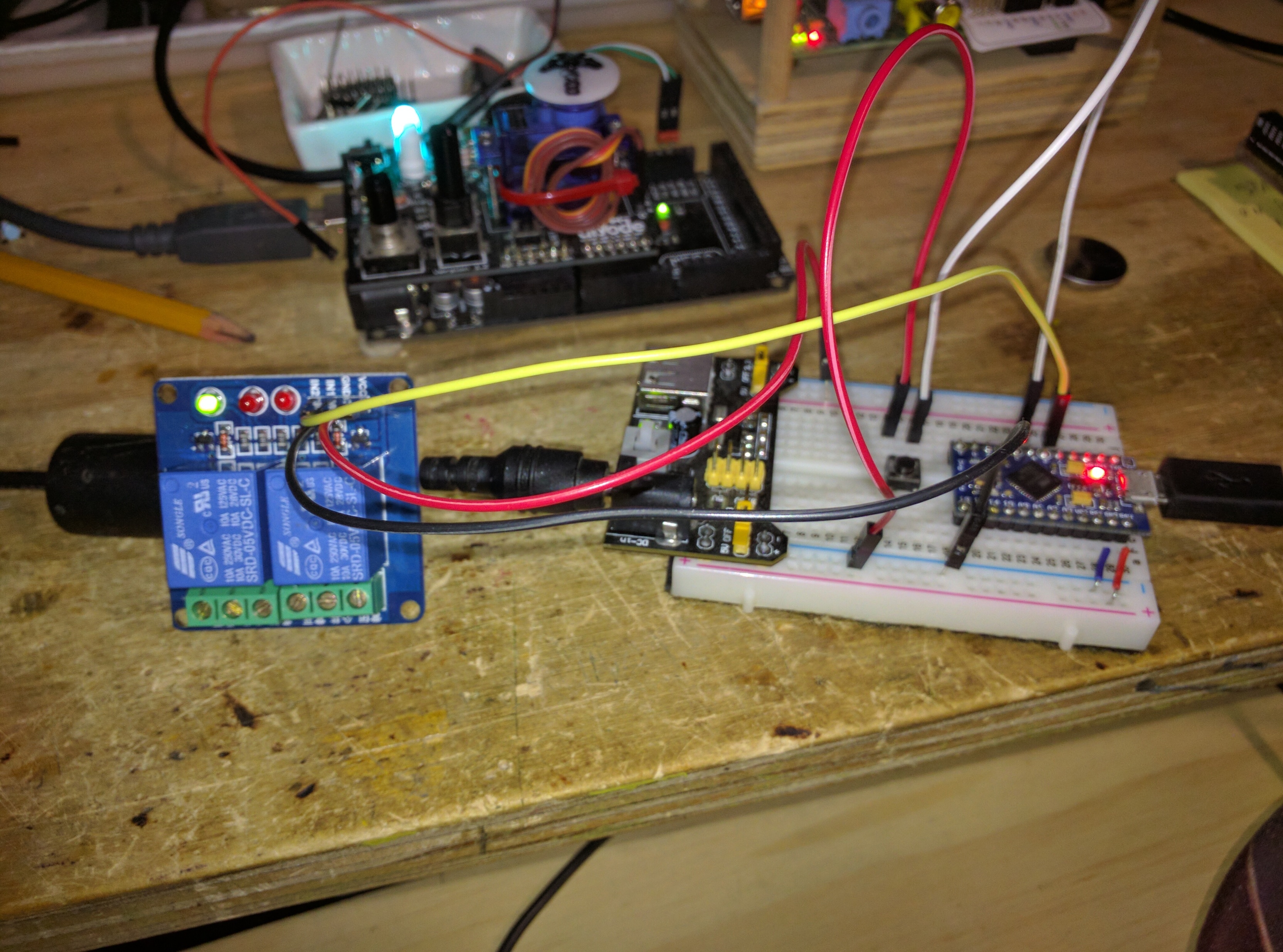
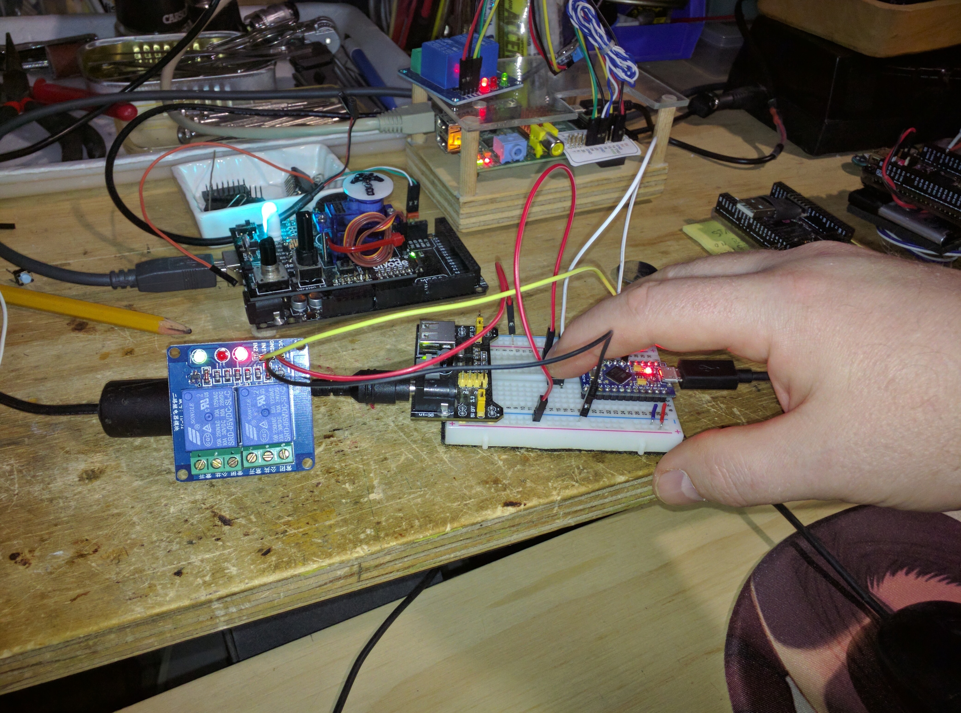
But please correct me if i am wrong. Right now the way its plugged in, the relay is being powered by 3.3v from the power supply. Its working fine. However, when i switch it to the 5v pin on the power supply, the relay stops working, it does not click. I have attached a picture.
You forgot to ground your MCU to the relay ground.
5v -> Relay Vcc & MCU Vin
GND -> MCU and Relay GND
Digital Pin from MCU -> Relay Signal in
this is all you should need