Where is the problem when I trigger a 5V relay with 3.3V?
If you are linking the ESP with a 5V Arduino then the normal 5V activated relays should be fine. Just take care how you hook up the connections between the ESP and the Arduino. Probably OK but ESP’s are 3.3V devices and Arduino’s (except the Mini) are 5V devices.
I have never used a nodemcu and prefer the WeMos. Either nodemcu is more popular than a WeMos, nodemcu’s have more problems than the WeMos or WeMos users are brighter  but we seem to see more problems on this site with the nodemcu than we do the WeMos.
I received an email only yesterday from a company that does a lot of work with ESP’s and without any prompting they said they prefer WeMos to nodemcu.
At the end of the day a WeMos is just a clone of the nodemcu so there is very little to choose between them.
All I can say is probably. Like most Ebay listings there are no details of what they are actually selling.
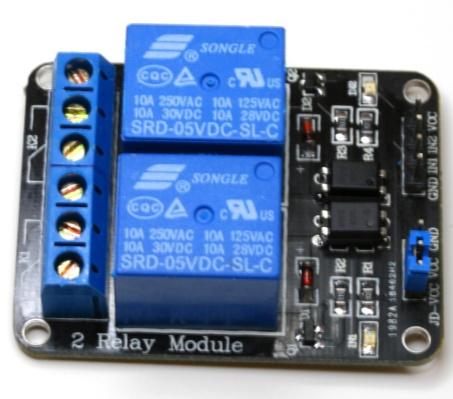
They have included ESP8266, NodeMCU, Arduino ARM in the title listing as a catch all for anyone searching for a relay for their MCU. All it says is 5V. An ESP working at 3.3V will probably trigger the relay but without seeing the full specification it’s difficult to say.
Looks like they are out of stock but I would just send an Ebay question asking them to guarantee that it will work with 3.3V MCU’s. If they are not prepared to guarantee, keep shopping.
These look ok for 68 cents including slow delivery but the same question applies.
@psoro can probably recommend a Far Eastern supplier of relays that 100% certain works at 3.3V. He might even have given me a supplier previously.
Take a look at one of @psoro’s projects at Automatic scheduler. ESP-01 with 4 Time Input Widgets
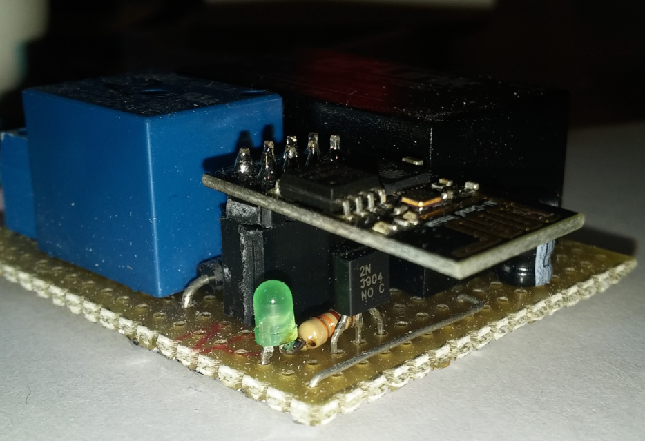
There is a link to bare 3V relays and @psoro uses a transistor to switch the 5V relay from a 3.3V ESP01.
I will check thanks.
But what do you think about logic level converter from 3.3V to 5V?
I would buy the correct relay and forget logic converters.
Do you think I’m crazy @Tom?
Look through the whole thread, the link is there.
It’s a thread you should read several times if you are planning to work with relays.
@Tom
Look at this on eBay http://www.ebay.com/itm/351748538371
@Costas, you have the patience of a… Saint? ^^
1 Like
now i have it:
SRD-03VDC-SL-C 3V DC
And you think these relay i can trigger direct with GPIO without any additional condensator or something else?
@Costas,
Not sure about this conversation regarding 3.3V relays…All relays I have are 5V… But I’m a little bit sleepy at this time… …I could be wrong
@Tom,
There are boards with optocoupler, I’ve got one of them and it works fine at 3.3V
1 Like
You are generally correct ![]() … Usually 5v, 12v or even 24v coils, but almost all with 5v logic triggering, that may or may not be 3.3v compliant (cheap design may skimp on that). Industrial relay logic gets into 5-24v triggering compliance, but that’s another issue
… Usually 5v, 12v or even 24v coils, but almost all with 5v logic triggering, that may or may not be 3.3v compliant (cheap design may skimp on that). Industrial relay logic gets into 5-24v triggering compliance, but that’s another issue ![]()
@Costas is correct, don’t bother until you know what you are getting into… LL Converters are necessary when sharing data lines between 3.3v and 5v devices, but not critical when triggering relays.
A relay will either trigger on 3.3v or it won’t… most will as the mid-point (between OFF and ON) in a typical 5v logic signal is 2v-2.5v, but some cheap relays are just cheap ![]()
I 2nd that !! ![]()
Has this topic been solved yet? it seems to have migrated into an “ask @Costas” thread… HEY! Now that is a great name for a Category Label ![]()
1 Like
Can someone explain me why when i trigger with Timer Wiget for example
Start 20:00:00, Stop 20:00:02 the signal goes HIGH but do not go back by Stop at 20:00:02.
In the description i can read that the stop signal is will be LOW.
BLYNK_WRITE(V6)
{
digitalWrite(13, HIGH); // GPIO13
}
It’s because your virtual pin V6 has the value low/High according to your timer but you never use it in your digital write.
Should be something like this
digitalWrite(13, param.asInt());
1 Like