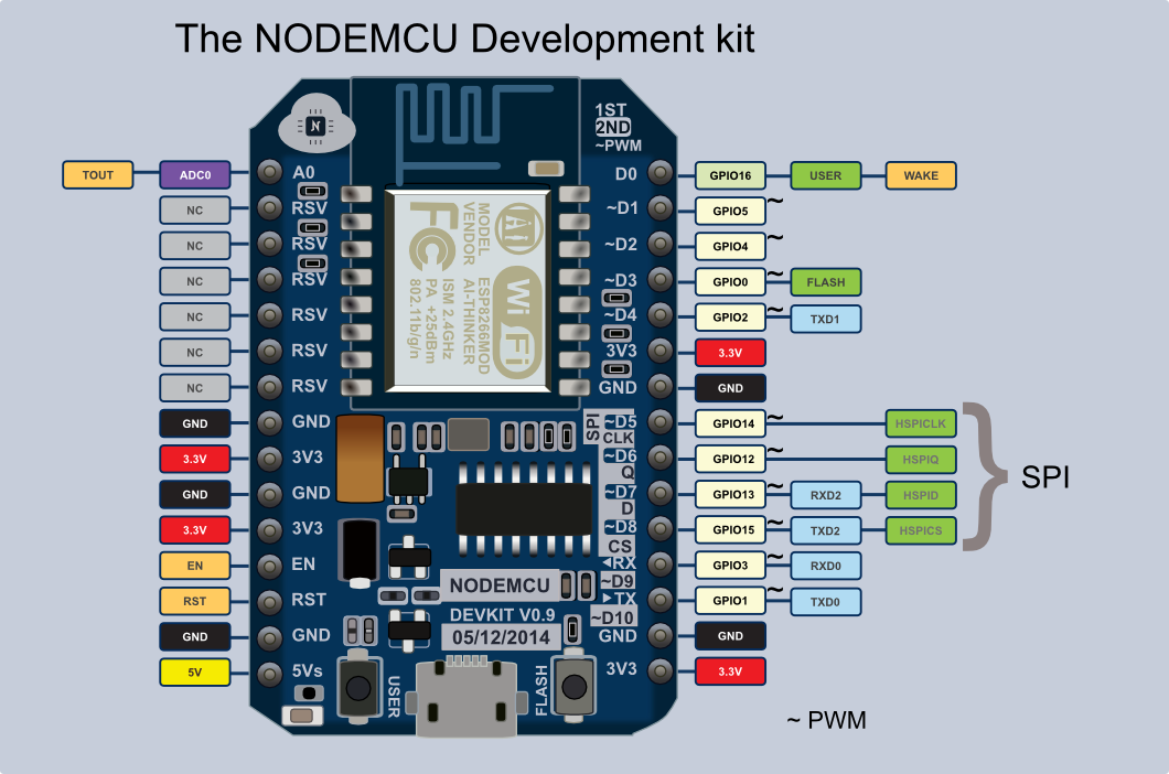
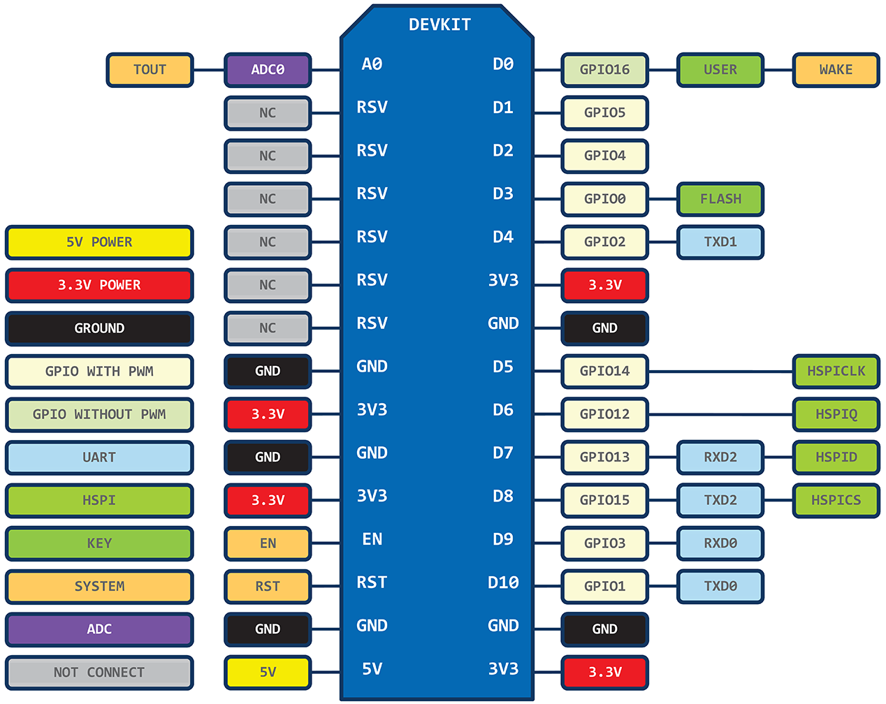
D1 is not pin 1, generally D1 is pin 5.
See http://cdn.frightanic.com/blog/wp-content/uploads/2015/09/esp8266-nodemcu-dev-kit-v1-pins.png for pin details.
D1 is not pin 1, generally D1 is pin 5.
See http://cdn.frightanic.com/blog/wp-content/uploads/2015/09/esp8266-nodemcu-dev-kit-v1-pins.png for pin details.
Chris, best to get Blynk connecting to the wifi before trying my code.
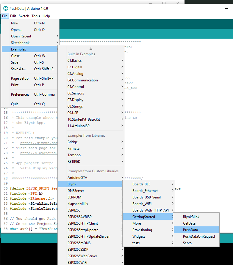
Use the PushData example first… get it working… create an understanding of how Blynk connects and get used to the app and adding widgets.
Once you have it connected to Blynk, and you can see the UP TIME counter moving on the app… then you can copy the auth code and wifi settings on to the LED project.
First thing you need to know is the SSID and PASSWORD to your normal wifi network you would use on your phone.
The SSID is the name of the network.
Once you have both of these, put them in to the code where it asks you. Then enter your auth code from the app.
Give that a go first and let us know how you get on!
And Coatas is correct, the Digital Pin numbers on the board do not translate to Arduino.
Refer to the image: See how D1 is actually GPIO5 (or pin 5) and D7 is GPIO13 or pin 13 in arduino (not pin 7)
thank you @jamin, i have use the PushData, but i have write only my AuthToken in, where i can write my ssid and pass in?
i have used the ESP8266_standalone sketch, and i can turn on and off the led with the blynk app, it works.
i dont know why your code in post 3 dont work, its not connecting with the blynk app.(i have put the AuthToken, ssid and pass in the code)
im going crazy :S
@Chriss255 for the sketch in post 3 look for this line:
Blynk.begin(auth, "xxxxxxxxxxxxxx", "xxxxxxxxxxxxxxx", IPAddress(192, 168, 1, 2));
First set of xxxxx’s are SSID and second are password. If you are running a local server change the IP address and ensure you use commas between the numbers not full stops. If you are using the Blynk’s cloud server remove:
, IPAddress(192, 168, 1, 2)
The PUSH data example is for Ethernet connections not WiFi.
When you are looking at the examples you need to modify them for your method of connection.
That is why there is an example for every conceivable type of connection.
Easy to change them once you get used to it.
You can send me actual code for your project? I scan Your QRcode and see “Menu” attached to V25. In your example it has described at V25 = Wifi Signal (Value Widget). Is a mistake?
Yeah I’ve made loads of changes since I made this thread and didnt know that the QR code links to the updates.
Here is the more recent code.
Thank you very much. Could you still generate a new qr code? The above seems to be to another project. Your code saves me a lot of work. Thanks.
Wow looks nice. Look at my last post 
Sorry my phone is currently dead and i have no charger. So I will have to post it later on.
You can easily recreate the widgets youtself using the info at the top of the sketch.
I know. Very thanks for good documentation. However, I would like to see the work of a master
Hey! Can You send my this QR code pls?
Very very thanks master
@Jamin Are there any errors you have encountered? I have problems when the update is too high. The board is unresponsive very often. The board does not reset, it doesn’t respond to the blynk app. I need to press a button 20 times before it responds.
I am going to keep as many delays out.
I still use this code on a 4MB version of the ESP8266 Dev.
I also have these which it works on perfectly.
What are your errors? and board?
I use WeMos D1 R2.
When I use the preset whitescan the whole board is unresponsive and need to press really fast on a manual button to get back, but after that, the whole system is not responsive again. Now I have deleted this preset in the code. But when the uptime is too high, it will become also unresponsive.
I think this is because of the delays.
Ohh yes!! Sorry lol I forgot about that!! Untouched bug. I never use different modes other than the first one.
If you can work it out and keep the pattern then please post it here!
I also want to implement my wake up light code in this project. To fade the lights in from the moment I have set the event timer.
http://community.blynk.cc/t/need-help-by-making-wake-up-light-with-wemos-d1-r2-tea5767-fm-radio
BTW, is there a way to dim the FastLED preset full_rainbow?
All the other presets have a variable in the constructor to control the brightness.

