ok, if anyone interested, here is of what i came up in the end.
the task was this:
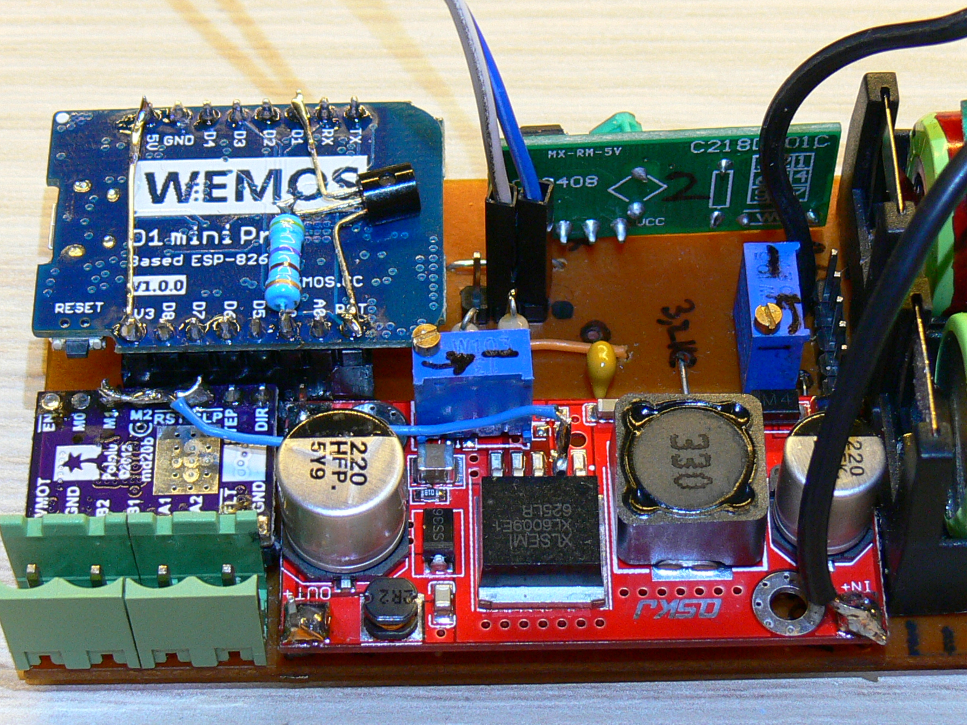
this is the whole circuit: 4 lithium cells (not shown), 12v->30v booster, stepper driver, 433mhz rx module, wemos, adjustable voltage divider aka 1Mohm trimpot ![]() for battery level monitoring on A0, and other misc components.
for battery level monitoring on A0, and other misc components.
basically, i’m minimalist, and the empty space on the pcb is not too much. so i’ve opted to use as few hardware components as possible for the standby function.
this is how it works:
when ESP.deepSleep(0); is executed, the wemos turns the D0 pin high. this officially should be wired to the RST pin, to be able to wake up the mcu.
but, because i do not need a timed wake up and according to the wemos schematic the RST pin anyway has a 100k pullup, it is not needed to wire the D0.
i have used a very common 2n2222 transistor and a ~400 ohm resistor. the transistor base via resistor is wired to D0.
the emitter is hooked up to the RST pin, and the collector to D1 (which in my case is the input pin for the reed relay, receiving a LOW signal when the magnet passes near the reed relay)
function:
-
in void setup D0 is set to output low, so it will turn off the transistor as soon as the wemos starts, and will keep it this way until…
-
…this code is executed:
if (deltaRPM > STANDBY && deltaSPD > STANDBY) {
Blynk.virtualWrite(TRIP, “STANDBY”);
if (blynkAllowed) Blynk.run();ESP.deepSleep(0); delay(100);}
-
the esp will turn D0 high then falls asleep. D0 turns on the transistor. the RST pin is pulled up high by the built in 100k pullup. the system is in deep sleep.
-
when the bike begins to move and the magnet on the wheel closes the relay, GND will be connected to the transistor, so the RST pin will receive a LOW signal and will reset the board.
-
as the board starts up, D0 will go LOW, turning off the transistor, so blocking the further resets every time the magnet passes near the relay.
the standby timer is adjustable from the blynk app.
measured current in standby: ~450 microamperes.