Hello fellow Blynkers!
This is my first post, but I’ve been lurking around this Forum for awhile now just reading about all the really cool projects others have made. I’m not new to the Arduino world, but I’m more of a hardware guy, The coding side of projects like these used to make my head hurt, but less so now that I’ve learned to use the BLYNK app.
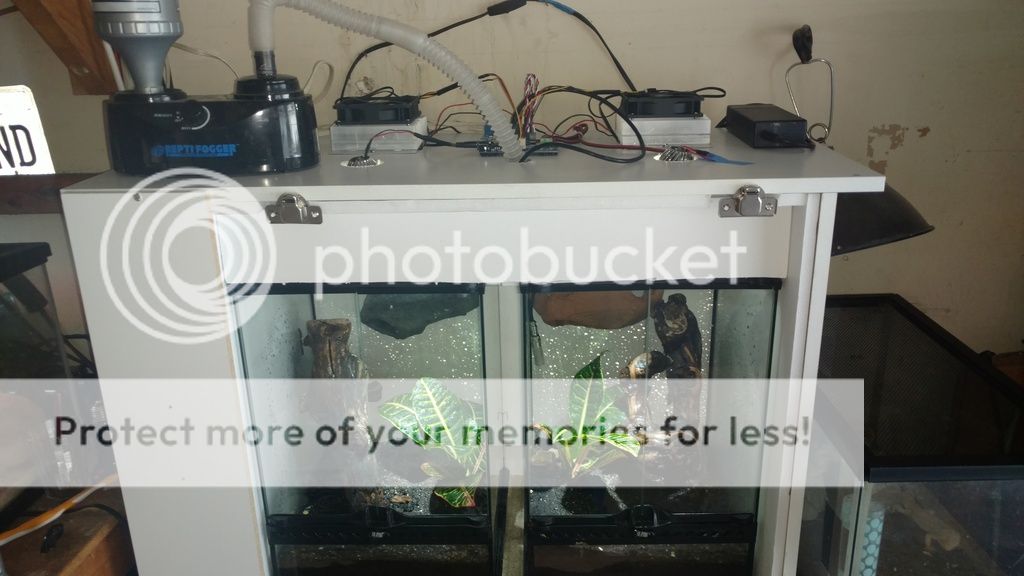
Long story short… I’ve got a wife and two kids. The kids love reptiles. The wife not so much. Because of this, my wife banished the reptiles from the house to the garage. The garage is fine, but Humidity & Temperature levels vary a lot. It’s not a good place for reptiles. The reptiles ( Crested Geckos) needed stable conditions. That’s were I came to the rescue… armed with an Arduino Uno, a DHT22 sensor, some relays, and a couple 12V automotive Heater/Cooler assemblies ( Peltier devices sandwiched between two large aluminum heat sinks). That was 3 years ago, and the Geckos are fine, but since I discovered BLYNK, a standard Arduino controlled life support system just won’t do.
Enter BLYNK… Time to re-vamp the whole thing!
Equipment used-
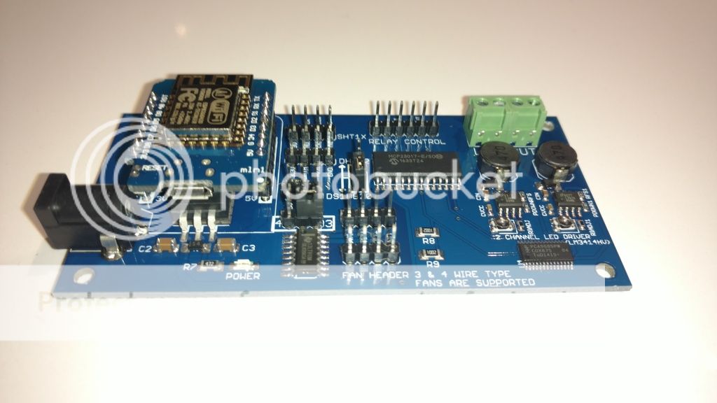
(1) WEMOS D1 Mini
(1) MCP23017 I/O port expander IC
(1) 4 channel Relay board (active LOW)
(1) 60 watt automotive Heater/Cooler assembly
(1) 12V 8 amp desktop power supply
(2) 90mm PC cooling fans ( one mounted to each side of the heat sink for air movement)
(1) Sensirion SHT10 Humidity/Temperature sensor ( bought the Adafruit version. Pricey but it’s robust construction is worth it)
The Code…(with only 3 lines in the ‘loop’() )
/* TERRARIUM HVAC CONTROL - Using the Sensirion SHT10 Humidity/Temp sensor.
Humidity & Temperature levels are checked, and logic is used to determine
if measured Humidity and/or Temperature parameters require adjustment.
All control commands are sent via I2C to an MCP23017 I/O port expander to save precious I/O pins on the ESP8266.
All relay control signals are held HIGH before being driven LOW to activate 4 "active LOW' relays.
One Relay controls the Humidifier's A/C line directly.
Two relays are used to toggle the direction of 12V current through a 60watt peltier device.
The relays are wired in such a way that both the Peltiers positive & negative wires are on the ground side of the circuit when the relays are at rest.
a Heating or Cooling command causes one of the two relays to switch ON, passing +12V through the Peltier device in one direction only.
WORK IN PROGRESS
need to ADD------
auto save settings to EEPROM - DONE
WiFiManager autoconnect AP and BLYNK TOKEN (needed for login to Blynk server)- DONE
BLYNK WIDGETS...i.e
RTC- Time(V4) Date(V2)- DONE
Read Teperature/Humidity data using a Sensirion SHT10 sensor. - DONE
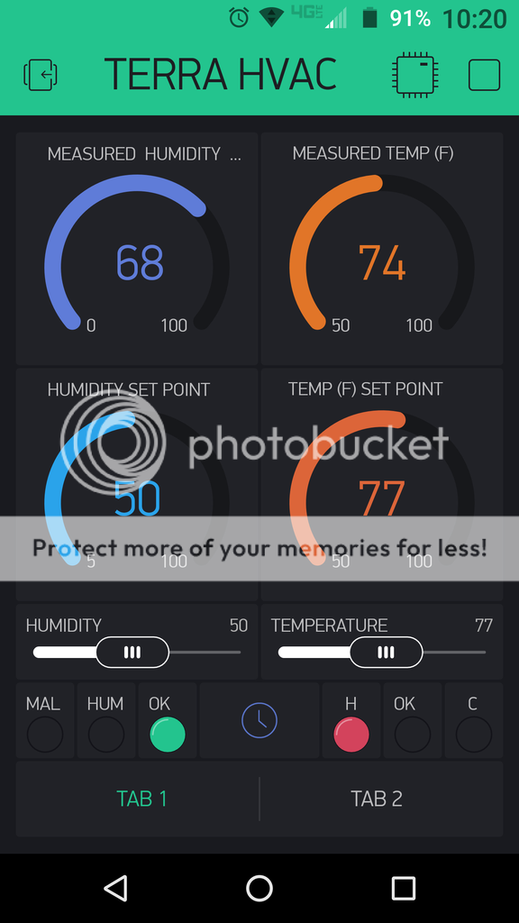
Humidity/Temp Gauges & Settings Sliders- DONE
Light (Spare relay) Overide switch. (Using Vitual button with BLYNK app)NOT DONE
Add ESP8266 OTA code to sketch - DONE
Temperature and Humidity Relay control functions via MCP23017 port expander.- DONE
Spare channel relay control for external A/C light control- NOT DONE
4 channel PWM LED lighting control logic (PCA9685 Based)- NOT DONE
*/
#include <FS.h> //this needs to be first, or it all crashes and burns...
#define BLYNK_PRINT Serial // comment this out to save space
#include <SPI.h>
#include <BlynkSimpleEsp8266.h>
#include <SimpleTimer.h>
#include <Wire.h>
#include <Centipede.h> // Library used to control the MCP23017 port expander chip.
#include <ArduinoOTA.h>
//included libraries for WiFiManager - AutoConnectWithFSParameters
#include <DNSServer.h>
#include <ESP8266WebServer.h>
#include <WiFiManager.h> //https://github.com/tzapu/WiFiManager
#include <ArduinoJson.h> //https://github.com/bblanchon/ArduinoJson
#include <EEPROM.h>
//added for RTC Widget (BLYNK app)
#include <TimeLib.h>
#include <WidgetRTC.h>
//added from Sensirion library for use with the SHT10 Humidity/Temp sensor
#include <Sensirion.h>
//LED status indicator widgets
WidgetLED led1(V8); //register to virtual pin V8 used for HUMIDIFIER ON/OFF indication
WidgetLED led2(V9); //register to virtual pin V9 used for HEATER ON/OFF indication
WidgetLED led3(V10); //register to virtual pin V10 used for COOLER ON/OFF indication
WidgetLED led4(V11); //register to virtual pin V11 used for SHT1X sensor malfunction indication
WidgetLED led5(V12); //register to virtual pin V12 used for TEMP IN RANGE indication
WidgetLED led6(V13); //register to virtual pin V13 used for HUMIDITY IN RANGE indication
// Sensirion sensor constants and variables.
const uint8_t dataPin = D0; // SHT serial data
const uint8_t sclkPin = D3; // SHT serial clock
const uint32_t TRHSTEP = 5000UL; // Sensor query period
uint16_t rawData;
byte measActive = false;
byte measType = TEMP;
unsigned long trhMillis = 0; // Time interval tracking
Sensirion sht = Sensirion(dataPin, sclkPin);
// Humidity and Temperature variables
unsigned int desiredHum = 0; // variable used to store the setpoint value for the desired humidity, once the measured humidity is lower than this value - the humDiff, start humidification.
int desiredTemp = 0; //variable used to store the setpoint value for the desired temperture, once the measured temperture is more/less than this value (+/- the tempDiff), heating or cooling will be activated.
int PreviousdesiredTemp = 0;// variable used to compare curent desired Temperature setting with the stored EEProm value.
int tempDiff = 3; // the +/- temperature differential.
int humDiff = 5; // a negative differential that's used to prevent constant humidifier relay cycling near the desired setpoint.
float temp = 0;// the temperature reading from the SHT10 sensor
float humidity = 0;// the humidity reading from the SHT10 sensor
int PreviousdesiredHum = 0;// variable used to compare curent desired Humidity setting with the stored EEProm value.
char blynk_token[34] = "YOUR_BLYNK_TOKEN";//added from WiFiManager - AutoConnectWithFSParameters
//flag for saving data
bool shouldSaveConfig = false;
//callback notifying the need to save config
void saveConfigCallback () {
Serial.println("Should save config");
shouldSaveConfig = true;
}
Centipede CS; // From the Centipede library, it's functions are used to interact with the MCP23017 I2C I/O expander chip.
SimpleTimer timer;// From the SimpleTimer Library. it creates a timer object.
// All Relay Outputs correspond to PORT A pins on a MCP23017 chip at I2C address = 0x20;.
// All 4 Relay controlled loads are switched ON when MCP23017 outputs go LOW.
// Humidifier_Relay = GPA7 // the pin number of the Humidifier relay.
// Heater Relay = GPA6 // the pin number of the Heater relay.
// Cooler Relay = GPA5 // the pin number of the Cooler relay.
// Spare Relay = GPA4 // the pin number of the Spare relay.
//
// This function runs the SHT10 sensor and sends Humidity and Temperature values to gauge widgets in the BLYNK app.
// Humidity readings on (V5)
// Temperature readings on (V6)
void sendSensor()
{ // Read values from the SHT10 sensor
unsigned long curMillis = millis(); // Get current time in millis
// non-blocking calls to SHT10 sensor
if (curMillis - trhMillis >= TRHSTEP) { // Time for new measurements?
measActive = true;
measType = TEMP;
sht.meas(TEMP, &rawData, NONBLOCK); // Start temp measurement
trhMillis = curMillis;
}
if (measActive && sht.measRdy()) { // Note: no error checking
if (measType == TEMP) { // Process temp or humi?
measType = HUMI;
temp = sht.calcTemp(rawData); // Convert raw sensor data
sht.meas(HUMI, &rawData, NONBLOCK); // Start humidity measurement
} else {
measActive = false;
humidity = sht.calcHumi(rawData, temp); // Convert raw sensor data
logData();
}
}
// Don't send more that 10 values per second.
Blynk.virtualWrite(V5, humidity); // guage in BLYNK app showing "Actual Humidity" as reported by the DHT22 sensor.
Blynk.virtualWrite(V6, temp); // guage in BLYNK app showing "Actual Temp" as reported by the DHT22 sensor.
}
void logData() {
Serial.print("Temperature = ");
Serial.print(temp);
Serial.println(" F ");
Serial.print("Humidity = ");
Serial.print(humidity);
Serial.println(" % ");
}
///// Humidity & Temperature Slider & Gauge Widget functions. Used to set and provide eye appealing desired Humidity & Temperature gauge readout.
BLYNK_WRITE(V3) {// slider widget to set the desired Temp in BLYNK app.
desiredTemp = param.asInt();
Blynk.virtualWrite(V1, desiredTemp);// Gauge widget showing desired Temp In BLYNK app.
}
BLYNK_WRITE(V7) { // slider widget to set the desired Humidity in BLYNK app.
desiredHum = param.asInt();
Blynk.virtualWrite(V0, desiredHum);// Gauge widget showing desired Humidity In BLYNK app.
}
// Humidifier control functions-
void determineHumidifierOnOff()
{
/// logic used to determine whether or not relative humidity should be raised.
if (humidity < desiredHum - humDiff )// This function measures the humidity level and subtracts the differential (humDiff) and switches the humidifier on if the prpoer conditions are met. humDiff = 5 points under desired Humidity level.
{ // HUMIDIFIER ON
CS.digitalWrite(7, LOW);//Humidifier Relay ON. Pin# assigment corresponds to MCP23017 I/O PORT A register #'s
Serial.println("HUMIDIFIER ON");
led1.on();//HUMIDIFIER INDICATOR ON
led4.off();//MALFUNCTION INDICATOR OFF
led6.off();//DESIRED RANGE INDICATION OFF
}
if (humidity <= 0)// this function stops the humidifier if a non valid reading is received from the SHT1X sensor.
{ // HUMIDIFIER OFF
CS.digitalWrite(7, HIGH);//Humidifier Relay OFF. Pin# assigment corresponds to MCP23017 I/O PORT A register #'s
Serial.println("SHT10 Sensor Malfunction- HUMIDIFIER operation terminated");
led1.off();////HUMIDIFIER INDICATOR OFF
led4.on();//MALFUNCTION INDICATOR ON
led6.off();//DESIRED RANGE INDICATION OFF
}
if (humidity >= desiredHum)// this function stops the humidifier if the measured humidity is in the desired range.
{ // HUMIDIFIER OFF
CS.digitalWrite(7, HIGH);//Hunidifier Relay OFF. Pin# assigment corresponds to MCP23017 I/O PORT A register #'s
Serial.println("HUMIDIFIER OFF");
led1.off();//HUMIDIFIER INDICATOR OFF
led4.off();//MALFUNCTION INDICATOR OFF
led6.on();//DESIRED RANGE INDICATION ON
}
if (humidity >= desiredHum - humDiff)
{
led6.on();//DESIRED RANGE INDICATION ON
}
}
/*
Temperature Control function used to switch Heating/Cooling on/off by toggling the direction of current
through a 60 watt Peltier device. The fans used to provide heating or cooling are activated through a separate circuit, anytime current is flowing through the Peltier device.
*/
void determineHeatorCool()
{
/// logic used to determine whether or not heating or cooling is needed.
if (temp <= 0)
{ // HEATER/COOLER OFF This function stops Heating/Cooling if a non valid value is received from the SHT10 sensor.
CS.digitalWrite(6, HIGH);//Heater Relay OFF. Pin# assigment corresponds to MCP23017 I/O PORT A register #'s
CS.digitalWrite(5, HIGH);//Cooler Relay OFF
CS.digitalWrite(4, HIGH);//Spare Relay OFF
Serial.println("SHT10 Sensor Malfunction- HEATING/COOLING operation terminated");
led2.off();//HEATING INDICATOR OFF
led3.off();//COOLING INDICATOR OFF
led4.on();//MALFUNCTION INDICATOR ON
led5.off();//TEMP IN RANGE OFF
}
if (temp < desiredTemp - tempDiff)
{ // HEATER ON / COOLER OFF
CS.digitalWrite(6, LOW);//Heater Relay ON. Pin# assigment corresponds to MCP23017 I/O PORT A register #'s
CS.digitalWrite(5, HIGH);//Cooler Relay OFF
CS.digitalWrite(4, LOW);//Spare Relay ON
Serial.println("HEATING");
led2.on();//HEATING INDICATOR ON
led3.off();//COOLING INDICATOR OFF
led4.off();//MALFUNCTION INDICATOR OFF
led5.off();//TEMP IN RANGE OFF
}
if (temp > desiredTemp + tempDiff )
{ // HEATER OFF/ COOLER ON
CS.digitalWrite(6, HIGH);//Heater Relay OFF. Pin# assigment corresponds to MCP23017 I/O PORT A register #'s
CS.digitalWrite(5, LOW);//Cooler Relay ON
CS.digitalWrite(4, LOW);//Spare Relay ON
Serial.println("COOLING");
led2.off();//HEATING INDICATOR OFF
led3.on();//COOLING INDICATOR ON
led4.off();//MALFUNCTION INDICATOR OFF
led5.off();//TEMP IN RANGE OFF
}
if (temp > desiredTemp - tempDiff && temp < desiredTemp + tempDiff)
{ // HEATER OFF/ COOLER OFF.... TEMP IN DESIRED RANGE.
CS.digitalWrite(6, HIGH);//Heater Relay OFF. Pin# assigment corresponds to MCP23017 I/O PORT A register #'s
CS.digitalWrite(5, HIGH);//Cooler Relay OFF
CS.digitalWrite(4, HIGH);//Spare Relay OFF
Serial.println("TEMP = DESIRED RANGE");
led2.off();//HEATING INDICATOR OFF
led3.off();//COOLING INDICATOR OFF
led4.off();//MALFUNCTION INDICATOR OFF
led5.on();//TEMP IN RANGE ON
}
}
void spare()// Spare relay (GPAI/O4) saved for future use.
{
// CS.digitalWrite(4, HIGH);//Spare Relay OFF
}
WidgetRTC rtc;// REAL TIME CLOCK added to BLYNK app dashboard
// Digital clock display of the time
void clockDisplay()
{
// You can call hour(), minute(), ... at any time
// Please see Time library examples for details
String currentTime = String(hour()) + ":" + minute() + ":" + second();
String currentDate = String(month()) + " " + day() + " " + year();
Serial.print("Current time: ");
Serial.print(currentTime);
Serial.print(" ");
Serial.print(currentDate);
Serial.println();
// Send time to the App
Blynk.virtualWrite(V4, currentTime);
// Send date to the App
Blynk.virtualWrite(V2, currentDate);
}
void GetPresets() {// Pre-set Humidity/Temperature values are stored in ESP8266 memory.
if (desiredTemp != PreviousdesiredTemp) { //update the EEPROM if desired temperature has changed.
EEPROM.write(1, desiredTemp);
EEPROM.commit();
Serial.print(F("New desired temperature saved: "));
Serial.println(desiredTemp);
PreviousdesiredTemp = desiredTemp;
}
desiredTemp = EEPROM.read(1);
if ((desiredTemp < 50) || (desiredTemp > 100)) {
desiredTemp = 75;
Serial.println(F("No saved temperature setting."));
}
if (desiredHum != PreviousdesiredHum) { //update the EEPROM if desired temperature has changed.
EEPROM.write(2, desiredHum);
EEPROM.commit();
Serial.print(F("New desired humidity level saved: "));
Serial.println(desiredHum);
PreviousdesiredHum = desiredHum;
}
desiredHum = EEPROM.read(2);
if ((desiredHum < 0) || (desiredHum > 100)) {
desiredHum = 50;
Serial.println(F("No saved humidity setting."));
}
}
void setup()
{
// put your setup code here, to run once:
Serial.begin(115200);// Start serial communication....
Serial.println();
Wire.begin(); // start the I2C communication protocol
CS.initialize(); // initalize the MCP23017 I/O expander chip.
CS.portMode(0, 0b0000000000000000); // set all 16 pins on the MCP23017 port expander chip to OUTPUT (0 to 15)
CS.pinMode(7, OUTPUT); //SET PIN TO OUTPUT. Pin# assigment corresponds to MCP23017 I/O PORT A register #'s
CS.pinMode(6, OUTPUT); //SET PIN TO OUTPUT
CS.pinMode(5, OUTPUT); //SET PIN TO OUTPUT
CS.pinMode(4, OUTPUT); //SET PIN TO OUTPUT
CS.digitalWrite(7, HIGH); //(#1) HUMIDIFIER RELAY set to OFF when HIGH. Pin# assigment corresponds to MCP23017 I/O PORT A register #'s
CS.digitalWrite(6, HIGH); //(#2) HEATER RELAY set to OFF when HIGH
CS.digitalWrite(5, HIGH); //(#3) COOLER RELAY set to OFF when HIGH
CS.digitalWrite(4, HIGH); //(#4) SPARE RELAY set to OFF when HIGH
//Load any saved settings from the EEPROM
EEPROM.begin(20);
Serial.println(F("STARTUP : LOADING SETTINGS FROM MEMORY"));
Serial.println(F(""));
delay(1000);
// Simple Timer functions-
timer.setInterval(5000L, GetPresets);
timer.setInterval(1000L, sendSensor);
timer.setInterval(5000L, determineHeatorCool);
timer.setInterval(5000L, determineHumidifierOnOff );
timer.setInterval(5000L, clockDisplay);
timer.setInterval(10000L, spare);
ArduinoOTA.begin();
//The following code is borrowed from WiFiManager
//clean FS, for testing
//SPIFFS.format();
//read configuration from FS json
Serial.println("mounting FS...");
if (SPIFFS.begin()) {
Serial.println("mounted file system");
if (SPIFFS.exists("/config.json")) {
//file exists, reading and loading
Serial.println("reading config file");
File configFile = SPIFFS.open("/config.json", "r");
if (configFile) {
Serial.println("opened config file");
size_t size = configFile.size();
// Allocate a buffer to store contents of the file.
std::unique_ptr<char[]> buf(new char[size]);
configFile.readBytes(buf.get(), size);
DynamicJsonBuffer jsonBuffer;
JsonObject& json = jsonBuffer.parseObject(buf.get());
json.printTo(Serial);
if (json.success()) {
Serial.println("\nparsed json");
strcpy(blynk_token, json["blynk_token"]);
} else {
Serial.println("failed to load json config");
}
}
}
} else {
Serial.println("failed to mount FS");
}
//end read
// The extra parameters to be configured (can be either global or just in the setup)
// After connecting, parameter.getValue() will get you the configured value
// id/name placeholder/prompt default length
WiFiManagerParameter custom_blynk_token("blynk", "blynk token", blynk_token, 34);
Serial.println(blynk_token);
//WiFiManager
//Local intialization. Once its business is done, there is no need to keep it around
WiFiManager wifiManager;
//set config save notify callback
wifiManager.setSaveConfigCallback(saveConfigCallback);
//add all your parameters here
wifiManager.addParameter(&custom_blynk_token);
//reset settings - for testing
//wifiManager.resetSettings();
//set minimu quality of signal so it ignores AP's under that quality
//defaults to 8%
wifiManager.setMinimumSignalQuality();
//sets timeout until configuration portal gets turned off
//useful to make it all retry or go to sleep
//in seconds
wifiManager.setTimeout(180);
//fetches ssid and pass and tries to connect
//if it does not connect it starts an access point with the specified name
//here "TERRA-HVAC-AP"
//and goes into a blocking loop awaiting configuration
if (!wifiManager.autoConnect("TERRA-HVAC AP")) {
Serial.println("failed to connect and hit timeout");
delay(3000);
//reset and try again, or maybe put it to deep sleep
ESP.reset();
delay(5000);
}
//if you get here you have connected to the WiFi
Serial.println("TERRA-HVAC connected :)");
//read updated parameters
strcpy(blynk_token, custom_blynk_token.getValue());
//save the custom parameters to FS
if (shouldSaveConfig) {
Serial.println("saving config");
DynamicJsonBuffer jsonBuffer;
JsonObject& json = jsonBuffer.createObject();
json["blynk_token"] = blynk_token;
File configFile = SPIFFS.open("/config.json", "w");
if (!configFile) {
Serial.println("failed to open config file for writing");
}
json.printTo(Serial);
json.printTo(configFile);
configFile.close();
//end save
}
Serial.println("local ip");
Serial.println(WiFi.localIP());
Blynk.connect();
Blynk.config(blynk_token);
rtc.begin();
Blynk.syncAll();
delay(1000);
if (!blynk_token)
{
Serial.println("Failed to connect to Blynk server");
wifiManager.resetSettings(); //ESP.reset();
delay(1000);
}
}
void loop()
{
Blynk.run();
timer.run(); // Initiates SimpleTimer
ArduinoOTA.handle();
}
Here’s a shot of the tabs of my BLYNK project dash board. The second tab contains an Lcd display and four buttons for an led lighting PWM controller. I’m still working on the code for that, and will roll it into the main code when it’s completed. I’m hoping that someone else will find this project useful?